1. Frontal airbag package fundamentals
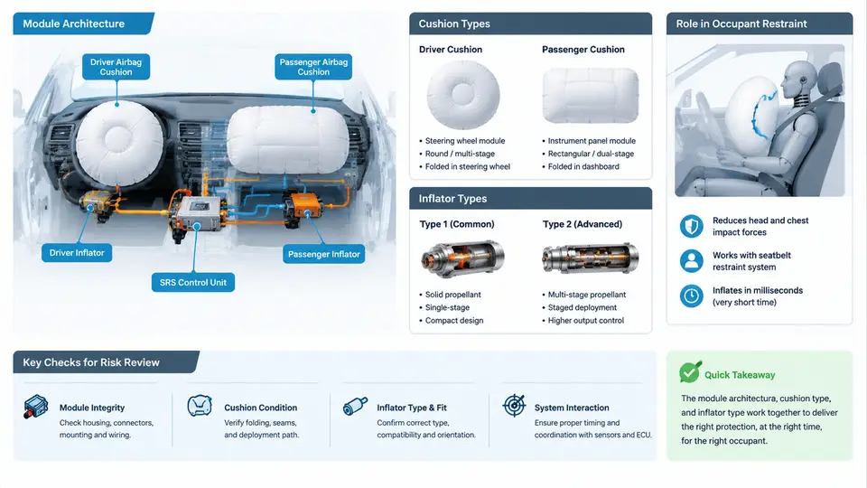
A frontal airbag package is not a single part but a small, tightly integrated restraint subsystem. Before any clearance or deployment-risk review can be meaningful, the reviewer must be able to read the package as a set of interacting components: the housing that carries structural load, the inflator that generates gas, the cushion that converts gas energy into a controlled pressure volume, the retainer and trim that manage the interface to the instrument panel or steering wheel, and the electrical harness and connector that arm the squib. Clearance and deployment risk are almost always consequences of how these elements relate to each other and to the surrounding vehicle structure, so the fundamentals in this chapter establish the vocabulary and the physical model used throughout the rest of the course.
Module architecture: what the package actually contains
A typical passenger-side frontal airbag module consists of a reaction can or housing, a inflator mounted inside or behind the housing, a folded cushion retained by a tear seam or a fabric retainer, a diffuser or heat shield, a chute or deployment door interface, and a mounting bracket set that ties the module to the cross-car beam or instrument panel substrate. Driver-side modules follow the same logic but are packaged inside the steering wheel hub, with the cushion folding pattern and the horn/trim interface replacing the instrument-panel door arrangement. In both cases the module is a pressure vessel during deployment: the housing must contain the inflator output long enough for the cushion to unfold, and the mounting strategy must transfer reaction loads into structure rather than into trim.
Three architectural relationships dominate later risk review. First, the inflator-to-housing interface determines where hot gas and particulate exit and how the housing reacts. Second, the cushion-to-housing retention determines whether the cushion stays attached under the initial pressure spike. Third, the module-to-structure mounting determines how the package moves during deployment and therefore how much clearance to adjacent parts is actually available. A package that looks acceptable in static CAD can still fail if any of these three interfaces is loaded in an unintended direction.
Cushion types and folding logic
Frontal cushions are broadly grouped by construction and by folding strategy. On construction, the common types are cut-and-sew cushions, where panels are sewn into a shaped bag, and one-piece woven (OPW) cushions, where the bag is woven as a single structure with an integral inflatable chamber. Cut-and-sew cushions allow complex shapes and internal tethers; OPW cushions reduce seam variability and are common where consistent unfolding is critical. On folding, the main families are accordion (Z-fold), roll-fold, and hybrid patterns. Roll-fold cushions tend to unfold outward and downward in a controlled sequence, which is often preferred for passenger-side packages where the cushion must travel across the instrument panel top before contacting the occupant. Accordion folds tend to deploy more directly along the module axis.
The folding pattern is not cosmetic. It sets the initial trajectory of the cushion, the order in which the cushion clears the housing and trim, and the timing of occupant contact. For clearance review, the key question is whether the folded cushion's initial expansion path intersects any rigid object — a trim edge, a display bezel, a steering-column shroud, or a cross-car beam — before the cushion has developed enough internal pressure to push past it. A cushion that contacts an obstruction early can be deflected, torn, or forced to deploy through an unintended gap.
Inflator types and their output characteristics
Frontal inflators fall into three practical families. Pyrotechnic inflators burn a solid propellant and produce gas quickly and at high temperature; they are compact and widely used where packaging space is tight. Hybrid inflators combine a small pyrotechnic charge with a stored compressed gas, which allows a lower flame temperature and a more gradual pressure profile. Stored-gas inflators release compressed gas with minimal combustion, giving the coolest and often the most controllable output, but they require a pressure vessel and careful thermal management. The choice of inflator affects the cushion's fill rate, peak pressure, and gas temperature, and therefore the severity of any interaction with nearby trim or structure.
For review purposes, the inflator should be characterized by its output curve — mass flow and pressure versus time — rather than by a single "output" number. Two inflators with the same total gas mass can produce very different early pressure spikes, and it is the early spike that most often drives trim rupture and cushion deflection. The inflator's mounting orientation and the diffuser design also matter: they determine where the gas jet impinges on the cushion fabric and whether hot particulate is directed toward a vulnerable surface.
Role in occupant restraint
The frontal airbag's job is to manage the occupant's forward motion in a crash by providing a compliant, energy-absorbing surface between the occupant and the vehicle interior. It does this in three phases: deployment, where the cushion inflates and clears the module; occupant loading, where the occupant compresses the cushion and the gas vents through vents or porous fabric; and energy dissipation, where the cushion and the restraint system together limit occupant deceleration. The package must therefore be sized so that the cushion is fully deployed before the occupant arrives, but not so stiff that it injures an out-of-position occupant. This trade-off is the reason clearance and deployment-risk review cannot be separated from occupant positioning and from the timing of the restraint system as a whole.
Reading the package as a system
The diagram above is the mental model to carry into every later review. The module envelope contains four interacting elements — inflator, housing, cushion, and retainer/trim — and the mounting brackets carry reaction loads into structure. The deployment chain on the right shows why clearance matters: the early pressure spike from the inflator is what ruptures the trim and drives the cushion outward, and the cushion's trajectory during that first phase determines whether it clears or collides with adjacent parts. The three interfaces called out at the bottom are where clearance and deployment risk concentrate, and they are the interfaces the following chapters will examine one by one.
A practical way to use this model is to build a short package data sheet before any clearance work begins. For a passenger-side module, that sheet should record the inflator part number and its validated output curve, the cushion construction and fold pattern, the cushion vent area, the housing material and wall thickness, the retainer type, the deployment door or tear-seam geometry, and the mounting bracket locations relative to the cross-car beam. For a driver-side module, replace the door geometry with the steering-wheel hub and horn/trim interface and record the clock-spring and harness routing. This sheet is not paperwork for its own sake: every later clearance finding traces back to one of these fields, and a missing field is itself a review finding.
What "good" looks like at the fundamentals stage
At the end of this chapter, the reviewer should be able to look at a frontal airbag package and answer four questions without opening a simulation: What inflator type is used, and what does its output curve look like in the first 20 ms? What cushion construction and fold pattern are specified, and in which direction does the cushion initially expand? How is the cushion retained, and what load path carries the reaction into structure? And which adjacent parts sit inside the cushion's initial expansion envelope? If any of these cannot be answered from the released data, the package is not yet ready for clearance review — the gap itself is the first finding.
The next step in the review process is to take this architectural understanding and convert it into a clearance envelope: a defined volume around the module that the cushion must be able to occupy without interference during deployment. That conversion, and the tolerances and stack-ups that define it, is where the fundamentals become an engineering method.