1. Crash pulse fundamentals
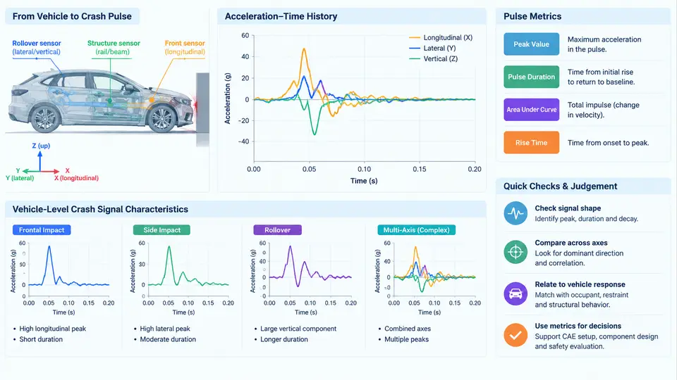
In a vehicle crash, the occupant is not directly loaded by the barrier or the striking vehicle. The load path runs from the contact interface, through the body structure, into the restraint system, and finally into the occupant. The crash pulse is the acceleration–time history measured at a structural location (typically the rocker, sill, B-pillar base, or seat track) that summarizes how the vehicle's velocity changes during that event. For structural design teams, the crash pulse is the single most important boundary condition: it defines the inertial loading that the occupant and every attached subsystem will experience, and it is the quantity that target cascading must decompose into structural stiffness, crush distance, and mass distribution requirements.
Acceleration–Time History and Sign Convention
A crash pulse is a time series a(t) recorded by an accelerometer, usually after low-pass filtering (commonly a 300–1000 Hz channel filter class per SAE J211/1, depending on the analysis purpose). Before any metric is computed, the sign convention must be fixed and documented. The most common convention in vehicle development is: positive acceleration points in the direction of travel (forward), so a frontal impact produces a predominantly negative acceleration pulse, because the vehicle decelerates. Some teams instead plot deceleration as positive. Both are acceptable, but mixing them across a program is a classic source of sign errors in target documents. This chapter uses the SAE-style convention: forward is positive, frontal impact pulses are negative, and "magnitude" refers to the absolute value.
Two derived quantities are used constantly. Velocity change is the integral of acceleration:
Δv(t) = ∫ a(t) dt        (from t = 0 to t = t_end)
Δv_total = v_impact − v_residual   (residual velocity after separation)
Displacement (crush) is the double integral. In practice, integration drift makes raw double integration unreliable, so the acceleration signal is typically baseline-corrected and the velocity curve is forced to the known residual velocity at separation. A pulse whose integrated Δv does not match the physically expected value (for example, 50 km/h barrier impact giving roughly 13.9 m/s before rebound) indicates a sensor, filtering, or baseline problem, not a structural insight.
Pulse Metrics That Drive Structural Targets
Engineers rarely cascade a full time history to structural teams. Instead, the pulse is reduced to a small set of metrics that can be written into targets and verified in CAE or sled tests:
| Metric | Definition | Typical use in cascading |
|---|---|---|
| Peak acceleration | Maximum |a(t)|, often reported over a defined window (e.g., first 30 ms) | Sets upper bound on local stiffness and attachment loads |
| Mean acceleration | Δv divided by pulse duration | Governs required crush distance for a given Δv |
| Pulse duration | Time from impact to separation or to a defined velocity threshold | Determines quasi-static vs. dynamic response of subsystems |
| Crush distance | Double integral of a(t), or measured deformation | Allocates package space to front/rear structures |
| Ride-down / pulse shape | Order and timing of acceleration peaks | Controls occupant deceleration ramp and restraint timing |
| Centroid time | Time-weighted center of the acceleration magnitude | Compact descriptor of where the pulse "sits" in time |
The relationship between mean acceleration, Δv, and crush distance is the workhorse equation of pulse-based target setting. For a constant-acceleration idealization:
s = Δv² / (2 · a_mean)
a_mean = Δv² / (2 · s)
As a worked example (illustrative numbers, not measured data): a 50 km/h frontal impact gives Δv ≈ 13.9 m/s. If the front structure is allocated 0.65 m of usable crush distance, the required mean deceleration is approximately 13.9² / (2 × 0.65) ≈ 149 m/s², or about 15 g. If packaging reduces crush distance to 0.50 m, the mean rises to about 19.3 g. This single calculation explains why early package decisions dominate the entire downstream target chain: crush distance is a geometric commitment, and every structural team inherits the acceleration level it implies.
Vehicle-Level Signal Characteristics
Real pulses are not smooth rectangles. A frontal pulse typically shows an initial sharp peak as the bumper beam and crash boxes engage, a dip or plateau as the rails fold, a second rise as the engine cradle and firewall region load up, and a final ramp as the occupant compartment decelerates. This shape is a direct fingerprint of the deformation sequence, which is why pulse shape—not just peak value—is cascaded to structural teams.
Three signal characteristics matter most when interpreting vehicle-level data:
- Frequency content. Structural ringing above roughly 100–200 Hz is usually filtered out for occupant-relevant metrics, but it still matters for component durability and sensor mounting. A pulse that looks benign after filtering can contain high-frequency content that fatigues brackets.
- Location dependence. The same event produces different pulses at the rocker, the tunnel, and the seat track. Targets must state the measurement location and axis explicitly; a rocker pulse is not interchangeable with a seat-track pulse.
- Event dependence. Offset, oblique, and pole impacts produce asymmetric and multi-axis pulses. A single frontal pulse cannot be used to cascade targets for small-overlap loading, where the load path and the resulting yaw and lateral acceleration are fundamentally different.
From Signal to Cascaded Requirement
The practical workflow is to convert the measured or CAE-derived pulse into a small target set, then distribute it. The figure below shows how a single vehicle-level acceleration history is decomposed into the metrics that structural teams actually receive, and how those metrics map onto different subsystem responsibilities.
Once the metric set is agreed, the cascade becomes a matter of allocation. Front structure teams receive crush distance and mean acceleration, because those define the energy absorption requirement. Occupant compartment teams receive peak acceleration and intrusion limits, because those define the survival space and attachment load cases. Restraint teams receive pulse shape and timing, because airbag and belt deployment must be phased against the deceleration ramp. Subsystem owners receive the high-frequency content and the attachment accelerations, because brackets and modules must survive the local environment even when the filtered occupant pulse looks mild.
Practical Verification of a Received Pulse
Before a pulse is used to set targets, run a short verification sequence. First, confirm the time-zero reference and align it with the barrier contact event. Second, integrate the filtered acceleration to obtain velocity and check that the final velocity matches the expected residual velocity within a few percent; a mismatch usually points to baseline drift or an incorrect filter. Third, compare the peak and mean values against the physical expectation from the crush distance equation above; a mean acceleration that implies more crush distance than the package allows is a signal that either the pulse or the package assumption is wrong. Fourth, check the measurement location against the target document, since a pulse from a different structural node can shift peak values by several g. Only after these checks should the metrics be written into the cascaded requirement set.
The crash pulse is therefore both a measurement and a contract. It records what the vehicle actually did, and it defines what every structural team must design for. Treating it as a carefully qualified signal—with explicit conventions, verified integration, and a documented metric set—is the foundation on which the rest of the target cascade depends.