1. Side impact barrier fundamentals
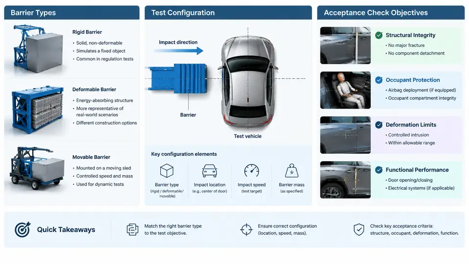
Side impact testing exists because the lateral load path of a passenger car is fundamentally different from its frontal load path. In a frontal crash, the vehicle has a long, dedicated deformation zone ahead of the occupant compartment. In a side impact, the distance between the striking object and the occupant is measured in tens of centimetres, and the structure available to absorb energy is limited to the door, the B-pillar, the rocker, the floor cross-members, and the side sill. The barrier is the controlled input that makes this short, violent event repeatable. Getting the barrier right — its type, its geometry, its mass, its velocity, and its alignment to the vehicle — is the precondition for any meaningful acceptance decision.
Why the barrier, not the vehicle, defines the test
A side impact test is only comparable across vehicles, labs, and model years if the moving or deformable object that strikes the vehicle is tightly specified. The barrier fixes three things at once: the kinetic energy delivered to the struck vehicle, the contact geometry (which determines where load enters the body side), and the stiffness profile of the striking face (which determines how the load rises over time). Change any one of these and the occupant response changes even if the vehicle is identical. This is why regulatory and consumer-test barriers are defined in standards down to face radius, honeycomb grade, and trolley mass, and why acceptance checks begin with barrier verification rather than with the dummy readings.
The principal barrier families
Three barrier concepts dominate side impact work, and they answer different engineering questions.
- Rigid moving barrier (RMB). A stiff, non-deforming face mounted on a moving trolley. Because the face does not crush, essentially all the trolley energy must be managed by the vehicle's side structure. The RMB is used where the intent is to probe structural intrusion and occupant loading under a well-defined, repeatable pulse — for example, the FMVSS 214-style moving deformable barrier tests and many OEM internal structural tests use rigid or near-rigid faces to isolate body-side performance.
- Deformable moving barrier (MDB). A trolley carrying a crushable honeycomb or aluminium-honeycomb-faced block. The barrier itself absorbs part of the energy and spreads the contact patch, producing a more realistic representation of a striking vehicle's front end. The MDB is the workhorse of regulatory side impact (ECE R95, FMVSS 214 MDB, and the side pole variants) and of consumer programmes, because it couples structural and restraint performance in a single event.
- Pole / fixed narrow object. A rigid cylindrical pole, either static with the vehicle moving or moving with the vehicle static. The pole concentrates load into a narrow band, which is the classic worst case for occupant-to-door interaction and for evaluating side airbag and curtain deployment timing. Pole tests are typically run at higher severity per unit of contact area and are used to check head and thorax protection where the striking object is narrow (trees, utility poles).
A fourth, less common family is the moving deformable barrier with a modified face (for example, a lower or offset face) used in OEM development to target specific body regions. These are development tools, not regulatory tests, and their acceptance criteria are set internally.
Test configurations and what each one measures
The barrier type is only half the configuration. The other half is the impact geometry: the angle of the barrier relative to the vehicle, the vertical position of the barrier face, the overlap, and the velocity. The table below summarises the configurations most often encountered and the engineering question each one answers.
| Configuration | Barrier | Typical intent | Key observable |
|---|---|---|---|
| 90° MDB side impact | Deformable moving barrier, perpendicular to vehicle | Regulatory / consumer side impact; combined structure + restraint assessment | Intrusion, dummy thorax/abdomen/pelvis response, door latch integrity |
| Rigid barrier side impact | Rigid moving face | Structural isolation; body-side energy management | B-pillar and rocker deformation, intrusion velocity |
| Oblique / angled MDB | Deformable barrier at an angle (e.g. 60°–75°) | Realistic intersection collisions; oblique load path | Occupant kinematics, belt and airbag interaction |
| Side pole (static pole, moving vehicle) | Rigid cylindrical pole | Narrow-object worst case; curtain airbag coverage | Head excursion, curtain coverage, pole intrusion |
| Moving pole (vehicle static) | Rigid pole on trolley | Repeatable pole loading; component-level checks | Localised intrusion, deployment timing |
Two conventions must be fixed before any of these are run, and they must stay consistent through the whole programme. First, the vehicle coordinate system: X forward, Y to the left, Z up, with the origin at a defined datum (commonly the front axle or the vehicle centreline at the front bumper). Second, the impact side: a "left-side impact" means the barrier strikes the vehicle's left side, and all intrusion and dummy-channel signs are reported in that frame. Mixing conventions between the barrier setup and the data reduction is one of the most common sources of false acceptance or false rejection.
Acceptance check objectives
Acceptance checks are not a single pass/fail number. They are a set of independent questions, each with its own evidence source, and a test is only accepted when all of them are answered. The objectives fall into four groups.
- Barrier and setup validity. Was the barrier the specified type, mass, face condition, and velocity? Was the alignment within tolerance? Was the vehicle at the specified attitude and tyre pressure? If any of these fail, the run is invalid regardless of the dummy results.
- Structural performance. Did intrusion into the occupant compartment stay within the defined limits at the specified measurement points (B-pillar, door inner, rocker, seat mount)? Did the door remain latched, and did the fuel system remain intact?
- Occupant protection. Did the dummy channels (head, neck, thorax, abdomen, pelvis) stay within the acceptance corridors, and did the restraint system — side airbag, curtain, belt — deploy and interact as intended?
- Repeatability and traceability. Were the instrumentation channels valid (no clipping, correct filtering per the standard, correct sign convention), and is the run consistent with the reference baseline within the allowed scatter?
How the pieces fit together
The diagram below shows the relationship between the barrier input, the vehicle response, and the acceptance decision. It is deliberately a signal-and-decision chain rather than a process flow: the point is that the barrier parameters propagate through the vehicle into the measured channels, and the acceptance logic compares those channels against limits that were fixed before the test.
A worked configuration example
Consider a development programme that needs to check the side structure of a mid-size sedan before a full regulatory MDB run. The team sets up a rigid moving barrier test as a structural screen. The barrier is a 950 kg trolley with a rigid face, run at 50 km/h (13.9 m/s), perpendicular to the vehicle, with the face centre aligned to the vehicle's mid-door height and the overlap set so the face covers the front and rear door region. The vehicle is at kerb weight plus a 75 kg driver-equivalent ballast, tyres at the specified pressure, and the impact side is the left side.
The expected observable is not a dummy pass/fail — this is a structural screen — but a set of intrusion measurements at the B-pillar base, the door inner panel, and the rocker, plus a check that the door remains latched. If the B-pillar intrusion exceeds the internal limit, the team knows the body side needs work before spending a full MDB run. If the barrier mass or velocity is found to be outside tolerance after the run, the intrusion numbers are discarded and the test is repeated, because the energy input was not the specified one.
What "acceptance" actually requires
The most common misunderstanding in side impact work is treating acceptance as a single dummy number. In practice, acceptance is a conjunction: the barrier must be verified, the structure must be within intrusion limits, the occupant channels must be within their corridors, and the run must be repeatable against the baseline. A run that passes the dummy channels but fails barrier verification is not an accepted run — it is an invalid run that happens to look good. The discipline of checking the barrier first, and refusing to interpret occupant data until the gate passes, is what makes side impact results trustworthy across a vehicle programme.
With the barrier families, the configuration geometry, and the four acceptance objectives established, the remaining chapters can treat each barrier type and each check in detail without re-litigating what the test is for.