1. Pole impact test fundamentals
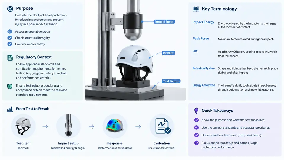
A pole impact test is a controlled collision in which a vehicle, or a test fixture representing a vehicle front structure, is driven into a rigid cylindrical pole at a defined speed and orientation. Its purpose is not to reproduce the most common crash on the road, but to concentrate crash energy into a narrow contact patch and expose the occupant compartment — and specifically the head — to a loading regime that flat barrier and offset deformable barrier tests cannot represent. This chapter establishes why the test exists, how it sits within the regulatory and consumer-rating landscape, and the vocabulary needed to read a head protection assessment without ambiguity.
Why a Narrow, Rigid Object Changes the Problem
In a full-width frontal barrier test, the vehicle front end distributes load across the entire bumper and rail structure. In a pole test, the same kinetic energy is absorbed through a contact width of roughly 250–350 mm. The consequences are structural and kinematic at the same time. Longitudinal rails may be bypassed entirely, so the pole loads the bumper beam, the lower cradle, and the firewall region directly. The resulting deceleration pulse is shorter and has a higher peak than a barrier pulse at the same impact speed. Because the pole is rigid and effectively immovable, essentially all of the deformation is imposed on the vehicle.
For head protection, the critical chain is: pole contact → localised front structure deformation → occupant compartment intrusion and/or a sharper rotational and translational occupant response → head contact with an interior surface or an external object. A pole test therefore probes two distinct failure modes. The first is intrusion-driven: the pole or deformed structure reaches the occupant space. The second is restraint-driven: the compartment survives, but the occupant's head is loaded by an airbag, a pillar, or a deploying side curtain in a way that produces unacceptable head injury metrics. Both must be assessed, and they require different instrumentation and different acceptance logic.
Regulatory and Rating Context
Pole impact requirements appear in several distinct frameworks, and it is important not to conflate them. In the United States, Federal Motor Vehicle Safety Standard (FMVSS) 201, Occupant Protection in Interior Impact, includes an oblique pole test originally introduced to address head injury in side-facing and angled impacts; it is conducted at 32 km/h (20 mph) into a 254 mm diameter rigid pole at a 75° angle, with a Hybrid III 50th percentile male dummy in the driver seat. In Europe, UN Regulation No. 135 (pole side impact) specifies a 32 km/h perpendicular or 32 km/h oblique pole test depending on the variant, with head, chest, and pelvis criteria. Consumer programmes add further variants: Euro NCAP's oblique pole test uses a 254 mm pole at 32 km/h with a 75° angle and a THOR or Hybrid III dummy, and evaluates head, chest, and abdomen responses against rating thresholds rather than pass/fail limits.
Two practical implications follow. First, the same physical event is judged by different criteria in different markets, so a test setup must declare its regulatory basis before any result is interpreted. Second, pole tests are frequently paired with side impact and rollover assessments because the head excursion and interior contact patterns overlap. A head protection assessment that ignores the pole configuration's angle and dummy type is not comparable to a published rating.
Key Terminology for Head Protection Assessment
The vocabulary below is used consistently throughout this course. Where a term has a regulatory definition, that definition governs.
| Term | Meaning in this course |
|---|---|
| Impact angle | Angle between the vehicle's longitudinal axis and the pole axis projected onto the ground plane; 75° denotes a predominantly side-facing oblique impact. |
| Pole diameter | Nominal rigid cylinder diameter, typically 254 mm; smaller diameters increase local pressure and intrusion severity. |
| Head Injury Criterion (HIC) | Time-integrated resultant head acceleration metric, HIC15 or HIC36 depending on the window; computed from the head CG triaxial accelerometer. |
| Head contact | Any physical interaction between the dummy head and an interior or exterior surface, identified from high-speed video and confirmed by acceleration signature. |
| Head excursion | Maximum displacement of the head CG relative to the vehicle interior reference frame during the event. |
| Intrusion | Permanent deformation of the occupant compartment boundary measured relative to the pre-test geometry. |
| Rigid pole | A pole whose stiffness is high enough that its own deformation is negligible; the test fixture must be anchored to resist the full impact load. |
| Dummy seating position | The designated seat and posture (driver, front passenger, rear outboard) that determines which restraint and interior surfaces are engaged. |
Two of these terms deserve emphasis. HIC is a scalar derived from acceleration over a time window, so the same peak acceleration can yield different HIC values depending on pulse duration; quoting HIC without the window is incomplete. Head contact is an event, not a metric — it must be localised in time and space before any injury metric is attributed to it. A high HIC without an identified contact surface usually indicates a restraint or instrumentation problem rather than an interior design problem.
From Event to Assessment: The Signal Chain
The figure below traces the physical event through to the assessment decision. It is deliberately a signal-and-decision chain rather than a process flow: each stage transforms data, and the branches show where a result can be invalidated before it reaches a head protection judgement.
What a Valid Test Requires Before Any Metric Is Read
Because the pole is rigid and the pulse is short, small setup errors dominate the result. Three checks should be completed before the head metrics are examined. First, confirm impact speed at the moment of contact — not at the trigger point — using a light gate or high-speed video; a 1 km/h error at 32 km/h changes kinetic energy by roughly 6%. Second, verify the pole anchor has not yielded; any pole base displacement invalidates the assumption of a rigid boundary and typically reduces measured intrusion while increasing head excursion. Third, confirm the dummy head accelerometer calibration date and the video frame rate are adequate to resolve contact timing, since a contact lasting a few milliseconds cannot be localised from 100 fps footage alone.
A useful sanity check is the acceleration signature itself. A genuine head-to-interior contact produces a sharp, short-duration spike with a clear onset; a restraint-induced loading produces a broader, lower-amplitude pulse. If the computed HIC is high but the video shows no contact and the acceleration trace is broad, the likely cause is a restraint deployment timing issue or a loose sensor mount, not an interior geometry problem. In that case the correct action is to inspect the mounting and the airbag firing record before re-running, rather than to adjust the interior design.
With this foundation — the purpose of the narrow rigid impact, the regulatory frameworks that define its parameters, and a precise vocabulary for head contact, excursion, intrusion, and HIC — the subsequent chapters can move into fixture design, instrumentation layout, and the detailed interpretation of head protection results.