1. Frontal crash configuration selection
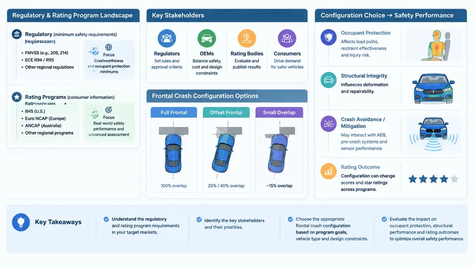
Frontal crash configuration selection is the process of deciding which impact conditions—barrier type, overlap percentage, impact speed, occupant and vehicle state—will be used to develop, validate, and certify a vehicle's frontal crash performance. It sounds administrative, but it is one of the highest-leverage engineering decisions in a safety program. A configuration defines the physical loading the structure and restraint system must survive, the injury metrics that will be judged, and the evidence that regulators, rating organizations, and customers will accept. Choose the wrong set, and a vehicle can pass one program while failing another, or optimize for a metric that does not represent the real-world crash population it is meant to protect.
This chapter establishes the landscape: the major regulatory and rating programs that define frontal configurations, the stakeholders who influence or consume the results, and why configuration choice is a performance decision rather than a compliance checkbox. Later chapters build the selection methodology, CAE and test workflows, and program-specific trade-offs on this foundation.
The program landscape: regulation versus rating
Frontal crash programs fall into two broad families. Regulatory programs are legally mandated; a vehicle cannot be sold in the jurisdiction without demonstrating compliance, typically through a self-certification or type-approval process backed by government-conducted or witnessed testing. Rating programs are voluntary or consumer-facing; they do not block sale, but they produce star ratings, scores, or awards that heavily influence purchase decisions, fleet procurement, insurance, and marketing. The two families often use different barriers, speeds, dummies, and injury criteria, so a single vehicle must satisfy a portfolio of configurations rather than one canonical test.
Three program archetypes dominate frontal work worldwide:
- Full-frontal rigid barrier (100% overlap): the vehicle strikes a flat rigid wall. This loads both longitudinal rails and the full front structure roughly symmetrically. It is the classic regulatory configuration in several markets and is comparatively repeatable, but it is not the most demanding case for occupant restraint because the deceleration pulse is distributed across the entire front end.
- Offset deformable barrier (ODB, typically 40% overlap): the vehicle strikes a honeycomb barrier covering part of the front. Only one side of the structure engages, producing asymmetric loading, yaw, and intrusion on the struck side. This configuration stresses structural integrity and occupant compartment survival far more than full frontal.
- Small overlap (typically 25% overlap, often against a rigid pole or barrier): a narrow strip of the front corner contacts the obstacle, bypassing the main rails. The load path runs through the wheel, suspension, and lower A-pillar region, and this configuration is notorious for producing severe occupant compartment intrusion and structural failure that full-frontal and moderate-overlap tests do not reveal.
Beyond these, programs may add pole impacts, moving deformable barriers, or angled frontal impacts. The key insight for selection is that these configurations are not interchangeable stress tests of the same structure—they exercise different load paths. A rail that performs well in full frontal may be irrelevant in small overlap, where the corner structure and wheel assembly carry the load.
Key stakeholders and what they actually need
Configuration choice is shaped by several stakeholders whose requirements can conflict:
- Regulators and type-approval authorities need demonstrable compliance with prescribed procedures, tolerances, and pass/fail criteria. They care about repeatability and legal defensibility.
- Rating organizations and consumer-test bodies need discriminative, comparable results across vehicles. They often push configurations that expose real-world weaknesses (small overlap being the canonical example) and publish scores that drive market behavior.
- Vehicle program and platform teams need configurations that are feasible within mass, cost, package, and timing constraints, and that align with the platform's architecture and load-path strategy.
- Restraint and occupant-safety engineers need configurations that exercise airbag, seatbelt, pretensioner, and load-limiter performance across the occupant sizes and seating positions the program targets.
- CAE and test organizations need configurations that can be modeled credibly and reproduced in the lab, with defined barrier, dummy, and instrumentation specifications.
- Fleet, insurance, and marketing stakeholders consume ratings and safety claims, so they influence which configurations the program prioritizes for evidence generation.
In practice, the selection decision is a negotiation: the regulator fixes a floor, the rating program sets an aspirational target, and the program team must find a structural and restraint design that satisfies both without unacceptable mass or cost. A configuration that is easy to pass but unrepresentative of real crashes is a poor choice even if it is legally sufficient.
Why configuration choice is a performance decision
The configuration determines the deceleration pulse the occupant experiences, the intrusion the occupant compartment must resist, and the injury metrics that will be judged. Change the overlap from 100% to 40%, and the pulse shifts from a broad, lower-magnitude event to a sharper, asymmetric one with yaw and struck-side intrusion. Change to 25% small overlap, and the main rails may never engage, so the corner structure and wheel must absorb energy—often a completely different design problem.
This is why configuration selection cannot be delegated to a compliance checklist. It is the point where the program decides which real-world crash modes it will design for, which load paths it will develop, and which evidence it will present. A well-chosen configuration set covers the dominant injury mechanisms (head, chest, and lower-extremity loading; occupant compartment intrusion; restraint timing) across the crash population the vehicle will actually face.
From landscape to selection: a worked framing
Consider a mid-size passenger car program targeting a global market. The regulatory floor includes a full-frontal rigid barrier test at a prescribed speed and an offset deformable barrier test. The consumer rating program adds a small-overlap configuration and a pole test. The program team must decide how much structural development to allocate to each load path.
A practical framing is to map each configuration to the structural and restraint systems it exercises, then assess coverage against the real-world crash population. For example, the full-frontal case is dominated by restraint timing and symmetric rail crush; the ODB case adds struck-side intrusion and yaw; the small-overlap case adds corner structure, wheel, and lower A-pillar loading. If the program's CAE and test evidence shows that the corner structure is under-developed, the small-overlap configuration becomes a priority even if it is "only" a rating test, because it exposes a real injury mechanism.
A simple coverage check can be expressed as a matrix of configurations against load paths and injury mechanisms, with each cell rated for evidence maturity (analysis-only, component test, full-vehicle test). The selection decision then becomes: which cells must be matured to full-vehicle evidence before the program gate, and which can rely on validated CAE plus component testing. This is the bridge to the methodology chapters that follow.
What "good" configuration selection looks like
A well-selected configuration set has four properties. First, it covers the dominant load paths: symmetric rail crush, asymmetric struck-side loading, and corner/wheel loading are all represented. Second, it covers the injury mechanisms the program cares about—head, chest, and lower-extremity loading, plus occupant compartment intrusion—across the occupant sizes and seating positions in scope. Third, it is reproducible: barrier, dummy, instrumentation, and setup specifications are defined tightly enough that CAE and test agree and results are comparable across builds. Fourth, it is defensible: the rationale for including or excluding a configuration is documented against regulatory requirements, rating program criteria, and the real-world crash population.
The rest of this course turns this framing into practice: how to build the configuration matrix, how to run the CAE and test workflows that populate it, how to interpret results against program-specific criteria, and how to manage the trade-offs when configurations conflict. The starting point is always the same—understand the landscape, know what each stakeholder needs, and recognize that the configuration you choose defines the crash you are designing for.