1. Regulatory landscape overview
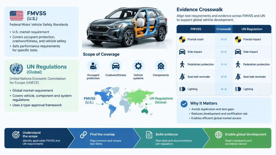
Vehicle safety compliance is rarely a single-market exercise. A body-in-white validated for the United States must often be re-evidenced for Europe, and increasingly for China, Japan, Korea, India, and the Gulf states. The two dominant regulatory families are the U.S. Federal Motor Vehicle Safety Standards (FMVSS), issued under 49 CFR Part 571 by NHTSA, and the UN Regulations annexed to the 1958 Agreement, administered through WP.29 and GRSP. They overlap substantially in intent — protecting occupants and other road users in crashes — but diverge in legal structure, test hardware, loading conditions, and acceptance criteria. Understanding those divergences is the foundation for any credible evidence crosswalk.
Two regulatory architectures, one safety objective
FMVSS is a self-certification regime. The manufacturer certifies that each vehicle complies, and NHTSA audits through random procurement and compliance testing. Each standard is a self-contained regulation: FMVSS 208 governs occupant crash protection, FMVSS 206 door locks and retention, FMVSS 214 side impact, FMVSS 216a roof crush, FMVSS 301 fuel system integrity, and FMVSS 305 electric energy storage. The standards specify barrier types, impact speeds, dummy types, and injury criteria in a single document, and they apply to vehicles sold in the U.S. regardless of origin.
UN Regulations operate differently. Each regulation is a discrete approval instrument, and type approval is granted by a designated authority in a Contracting Party, then recognized by other parties under the 1958 Agreement. UN R94 covers frontal impact, R95 side impact, R137 frontal offset with restraint systems, R127 pedestrian protection, R135 pole side impact, and R100 battery electric vehicle safety. The UN framework also includes the Global Technical Regulations (GTRs) — notably GTR 9 on pedestrian protection and GTR 20 on electric vehicle safety — which are not themselves approval instruments but are transposed into national law by contracting parties.
Where the regimes converge and where they diverge
At the level of physics, frontal impact protection in FMVSS 208 and UN R94/R137 both use a rigid or deformable barrier at approximately 56 km/h, with a Hybrid III 50th percentile male dummy in the driver position. But the details matter for evidence reuse. FMVSS 208 uses a full frontal rigid barrier at 56 km/h with belted and unbelted test configurations, and includes an offset deformable barrier test at 40 km/h in some configurations. UN R94 uses a 40% offset deformable barrier at 56 km/h, while R137 adds a full-width rigid barrier test at 50 km/h. The dummy seating procedure, the barrier face geometry, the pulse corridor, and the injury criteria thresholds (HIC, chest deflection, femur load, neck injury) differ in specific values and in how they are measured.
Side impact illustrates the same pattern. FMVSS 214 uses a moving deformable barrier at 54 km/h at 27° to the vehicle axis, with a SID-IIs dummy in the driver position and a ES-2re in some configurations. UN R95 uses a moving deformable barrier at 50 km/h perpendicular to the vehicle, with an ES-2 dummy. The barrier mass, face geometry, and impact angle are not interchangeable, so a test performed to one specification does not automatically satisfy the other.
| Domain | FMVSS instrument | UN instrument | Principal divergence affecting evidence reuse |
|---|---|---|---|
| Frontal impact | FMVSS 208 | UN R94, R137 | Barrier type, offset percentage, unbelted configuration, dummy seating |
| Side impact | FMVSS 214 | UN R95 | Barrier angle (27° vs perpendicular), barrier mass, dummy type |
| Pole side impact | FMVSS 214 (optional/limited) | UN R135 | Pole diameter, impact speed, dummy positioning |
| Roof crush | FMVSS 216a | UN R135 (partial), GTR 20 context | Force application plate, test speed, acceptance force |
| Pedestrian protection | FMVSS 228 (limited) | UN R127, GTR 9 | Legform and headform impactors, impact points, speed |
| Fuel system integrity | FMVSS 301 | UN R34 | Rear impact speed, fuel spill limits, post-impact orientation |
| EV battery safety | FMVSS 305 | UN R100, GTR 20 | Test sequence, thermal propagation requirements, isolation monitoring |
Why a crosswalk is not a translation table
A naive crosswalk maps FMVSS 208 to UN R94 and declares the evidence equivalent. In practice, three failure modes appear. First, test-condition mismatch: a 40% offset ODB test at 56 km/h does not produce the same structural loading as a full frontal rigid barrier test at 56 km/h, so the deformation pattern and occupant kinematics differ. Second, dummy and instrumentation mismatch: a SID-IIs and an ES-2 respond differently to the same side impact, and their injury criteria are not directly comparable. Third, evidence-form mismatch: a manufacturer's certification test report may not contain the traceability, calibration records, and technical service oversight that a UN type approval authority expects.
A defensible crosswalk therefore operates at three levels: regulatory mapping (which clauses correspond), technical equivalence assessment (whether the test conditions and acceptance criteria are sufficiently similar that one test can support both claims), and evidence sufficiency assessment (whether the existing documentation meets the procedural requirements of the target regime). Only when all three levels are satisfied can a single test campaign be used to support both FMVSS certification and UN type approval.
Practical implications for global vehicle development
For a program targeting both markets, the crosswalk should be built early — during the architecture and attribute-target-setting phase, not after the first crash test. The practical workflow is to enumerate the target markets, extract the applicable instruments from each regime, and then for each instrument identify the test conditions and acceptance criteria that drive the vehicle design. Where the conditions are close enough, a single test campaign can be planned with the more stringent condition as the design driver and the less stringent condition verified by analysis or by a reduced test matrix. Where they are not, separate tests must be budgeted.
Consider a concrete example. A mid-size SUV is being developed for the U.S. and EU markets. The frontal impact crosswalk maps FMVSS 208 to UN R94 and R137. The design team identifies that the UN R94 40% offset ODB test at 56 km/h produces the highest longitudinal intrusion demand on the toe board and dash panel, while the FMVSS 208 full frontal rigid barrier test at 56 km/h drives the restraint system tuning for the unbelted occupant. Neither test substitutes for the other, but both can be run on the same body-in-white with the same barrier facility if the test matrix is planned together. The evidence package then contains two test reports, each traceable to its own regulation, plus a crosswalk memo that documents why both were required and how the results jointly support the certification and approval claims.
What the crosswalk must capture
A working crosswalk is a living document with four columns that matter: the source requirement (regulation, clause, and test condition), the target requirement (regulation, clause, and test condition), the equivalence judgment (equivalent, partially equivalent, or non-equivalent, with rationale), and the evidence reference (test report number, approval certificate number, or analysis report). The equivalence judgment should be supported by a short technical note that names the specific parameters compared — barrier mass and geometry, impact speed and angle, dummy type and instrumentation, seating procedure, and acceptance thresholds — and states whether each is identical, within an acceptable tolerance, or materially different.
The crosswalk also needs a governance dimension. Because UN Regulations are amended periodically through WP.29 and FMVSS through NHTSA rulemaking, the crosswalk must record the regulation version or amendment level against which each judgment was made. A crosswalk built against UN R94 as amended by Supplement 3 may not hold against a later supplement that changes the barrier face or the injury criteria. Version control is therefore not administrative overhead; it is a technical requirement for the crosswalk to remain valid across a vehicle program's life cycle.
Finally, the crosswalk should distinguish between design evidence (CAE, component tests, sled tests) and compliance evidence (full-scale vehicle tests to the exact regulatory procedure). Design evidence is valuable for early trade-off decisions and can inform the crosswalk, but it cannot substitute for compliance evidence unless the target regime explicitly accepts it. Keeping this distinction explicit prevents the most common crosswalk failure: treating a CAE correlation study as if it were a certification test.
The remainder of this course builds on this landscape. Subsequent chapters will work through the individual instrument pairs in detail, develop the technical equivalence assessment method, and provide templates for the crosswalk document and the evidence package that supports multi-market certification and type approval.