3. Report structure and engineering standar
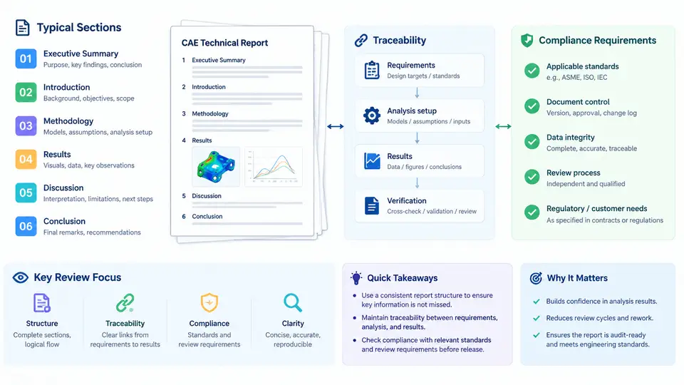
An AI-generated CAE report is only useful if a reviewer can navigate it, verify it, and sign it off. That requires a stable document skeleton, an unbroken chain from every claim back to its source data, and explicit conformance to the standards the project has agreed to follow. This section defines a reference structure, shows how traceability is encoded in practice, and gives a compliance checklist that a technical reviewer can apply directly.
3.1 A Reference Section Skeleton
Most structural, thermal, and CFD deliverables converge on the same logical order: state the problem, state the assumptions, show the model, show the results, then interpret them. The table below is a working skeleton that maps each section to its engineering purpose and to the evidence a reviewer will look for.
| Section | Engineering purpose | Reviewer evidence |
|---|---|---|
| 1. Scope & objectives | Define what is being qualified and to which criteria | Load cases, acceptance thresholds, referenced spec IDs |
| 2. Inputs & assumptions | Freeze geometry revision, material data, boundary conditions | CAD revision hash, material card source, BC table |
| 3. Model description | Document mesh, element types, contacts, solver settings | Element count, min/max Jacobian, contact formulation |
| 4. Verification | Prove the model solves the intended equations | Mesh convergence plot, energy balance, unit check |
| 5. Results | Present fields, histories, and extracted quantities | Contour plots with legend ranges, probe tables |
| 6. Validation & discussion | Compare against test or hand calculation | Correlation table, deviation percentage |
| 7. Conclusions & margins | State pass/fail and remaining margin | Margin of safety, governing load case |
| 8. References & approvals | Close the audit trail | Document IDs, revision, reviewer signature block |
Two conventions matter more than the exact numbering. First, verification and validation must be separate sections: verification asks "did we solve the equations correctly," validation asks "did we solve the right equations." Merging them is the single most common structural defect in AI-drafted reports. Second, every numeric claim in Sections 5–7 must be reproducible from Sections 2–4 without opening the solver GUI.
3.2 Traceability as a Data Structure, Not a Paragraph
Traceability means that for any reported number you can walk backwards: result → extraction location → load case → boundary condition → material property → source document. In practice this is implemented with stable identifiers rather than prose. A workable scheme uses a requirement ID, a model entity ID, and a result ID, linked in a traceability matrix.
REQ-014  "Bracket shall survive 15 g lateral load, no yield"
  └─ LC-003   load case: 15 g lateral, +X, 0.1 s ramp
       └─ BC-021  fixed at 4 bolt holes, RBE2 to ref node 9001
            └─ MAT-007  Al 7075-T6, E=71.7 GPa, Sy=503 MPa (MMPDS-01)
                 └─ RES-112  max von Mises = 431 MPa @ node 24517, t=0.1 s
                      └─ MS = Sy/(SF*sigma) - 1 = 503/(1.5*431) - 1 = -0.22  FAIL
Note the margin-of-safety convention used here: MS = allowable / (SF × applied) − 1, so a negative value is a failure. Whatever convention is chosen, it must be stated once in Section 1 and used identically in every table and figure. Mixing MS = allowable/applied − 1 with a factored form in the same report is a compliance defect even when the numbers are individually correct.
When an AI assistant drafts the narrative, it should be constrained to emit these identifiers verbatim. A useful guardrail is to require that every sentence containing a number also contains at least one ID token matching the pattern (REQ|LC|BC|MAT|RES)-\d+. Sentences that fail this check are flagged for human completion rather than silently published.
3.3 Compliance Requirements for Technical Review
Compliance is project-specific, but the categories are stable. A reviewer typically checks four families of requirements: document control (revision, approval, distribution), method compliance (solver version, element quality limits, convergence criteria), regulatory or contractual compliance (e.g., ASME BPVC Section VIII Div. 2 for pressure vessels, Eurocode 3 for steel structures, or a customer-specific stress report specification), and data integrity (units, significant figures, no orphaned results).
The following checklist is written so it can be pasted into a review record and marked pass/fail per line. It is deliberately short; a checklist that takes an hour to fill out will not be used.
| # | Check | Acceptance criterion |
|---|---|---|
| C1 | Units declared | Single consistent system stated in Section 1; no mixed mm/MPa with N·m |
| C2 | Solver and version recorded | Exact version string, e.g. Abaqus 2023 HF3 |
| C3 | Mesh quality reported | Min Jacobian, max aspect ratio, % elements above warning threshold |
| C4 | Convergence demonstrated | Residual or mesh-convergence curve with tolerance stated |
| C5 | Traceability matrix complete | Every REQ maps to ≥1 RES; no RES without a parent LC |
| C6 | Margins recomputed independently | Reviewer recalculates at least the governing MS by hand |
| C7 | Assumptions bounded | Each assumption has a stated validity range and a sensitivity note |
| C8 | Approval block signed | Author, checker, approver with dates and revision ID |
3.4 Worked Example: Reviewing a Bracket Report
Consider a deliverable for a satellite equipment bracket. The AI draft reports a maximum von Mises stress of 431 MPa under a 15 g lateral load and concludes "margins are adequate." A reviewer applying the checklist finds three defects. C1 fails because the material card is in MPa but the load table is in g and the geometry in inches. C5 fails because RES-112 has no parent LC in the matrix — the 15 g case was added after the matrix was frozen. C6 fails because the reported margin used MS = 503/431 − 1 = +0.17, omitting the required safety factor of 1.5; the correct value is −0.22, a failure.
The corrective action is not to rewrite the prose. It is to fix the matrix, re-run the extraction with the correct factor, and regenerate the affected figures. This is exactly the workflow where AI assistance pays off: the narrative and tables can be regenerated automatically once the underlying IDs and factors are corrected, provided the report was authored against a structured data source rather than free text.
3.5 Encoding the Structure for Automated Generation
To make the skeleton machine-checkable, store it as a template with required fields rather than as a Word outline. A minimal JSON schema fragment for one result block looks like this:
{
  "result_id": "RES-112",
  "parent_load_case": "LC-003",
  "quantity": "von_Mises_stress",
  "extreme_value": 431.0,
  "units": "MPa",
  "location": {"node": 24517, "time_s": 0.1},
  "allowable": 503.0,
  "safety_factor": 1.5,
  "margin_of_safety": -0.22,
  "verdict": "FAIL",
  "figure_ref": "FIG-007"
}
With this schema, the compliance checks C1, C5, and C6 become automated assertions: units must be non-null, parent_load_case must resolve, and margin_of_safety must equal allowable/(safety_factor*extreme_value) − 1 within rounding tolerance. The AI layer then only writes connective prose, and the reviewer's effort shifts from arithmetic to engineering judgment — which is where it belongs.
The structure, the identifiers, and the gates are what make an AI-assisted report reviewable. Once they are in place, the reviewer's job is reduced to the two questions that actually require an engineer: are the assumptions defensible, and is the governing load case the right one?