1. Full vehicle safety validation in PAM-CR
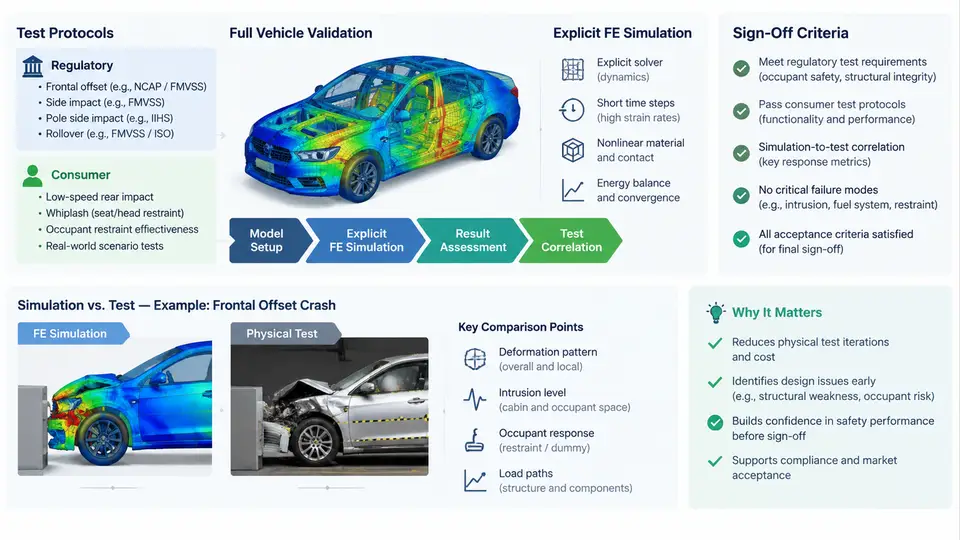
Full vehicle safety validation is the process of demonstrating, with evidence, that a vehicle structure and its restraint systems protect occupants and other road users across a defined set of impact scenarios. In modern vehicle programs, this evidence is assembled from two complementary sources: physical crash tests performed to regulatory and consumer protocols, and explicit finite element (FE) simulation, most commonly executed in PAM-CRASH. The simulation does not replace the test; it predicts the test, explains the scatter between tests, and supports the engineering decisions that make the final test pass on the first attempt.
Regulatory versus consumer protocols
Two families of protocols dominate the validation plan. Regulatory protocols define the legal minimum. They specify the impact configuration, the barrier or deformable element, the impact speed with a tolerance band, the dummy type and seating procedure, the measurement channels, and the pass/fail threshold. Typical examples include frontal offset deformable barrier (ODB) tests at 64 km/h, full-width rigid barrier tests at 50 km/h, and side impact tests with a moving deformable barrier at 50 km/h. Because they are legal requirements, the tolerances are tight and the outcome is binary: the vehicle is homologated or it is not.
Consumer protocols, such as Euro NCAP, C-NCAP, and IIHS, go beyond the legal minimum. They add higher severities, additional configurations (small overlap, oblique pole, far-side occupant), and a scoring system that rewards margin rather than mere compliance. A vehicle that just meets the regulatory threshold may score poorly. Consumer protocols also evolve on a roughly two-to-three-year cycle, which means the validation target must be set against the protocol revision expected at the planned start of production, not the revision current at program kick-off.
The practical consequence is that the load cases in the CAE deck must be traceable to a specific protocol revision. A common failure mode in early programs is a mismatch between the barrier geometry or impact angle used in simulation and the one defined in the current protocol text, which only surfaces when the physical test is scheduled.
Sign-off criteria and how they are structured
Sign-off criteria are the quantitative gates that a design must satisfy. They fall into three tiers. Injury criteria are the primary gates: Head Injury Criterion (HIC15), chest deflection and viscous criterion, neck tension and compression, femur force, and pelvis acceleration, each with a limit and, in consumer protocols, a higher-performance reference. Structural criteria cover occupant compartment integrity: steering column and pedal rearward displacement, dash panel intrusion, door opening force, and fuel system integrity. Restraint criteria cover airbag deployment timing, seatbelt load limiter force, pretensioner firing, and the absence of bottoming-out or bag slap.
In simulation, each criterion is evaluated from a filtered channel. The SAE J211 filter class matters: accelerations are typically filtered at CFC 60 for head and CFC 180 for chest, and applying the wrong class changes HIC by several percent. The sign convention must also be fixed before any result is read. In this course we adopt the standard convention that the vehicle longitudinal axis points forward (+X), lateral to the left (+Y), and vertical upward (+Z), and that occupant injury channels are reported as positive magnitudes regardless of the direction of the applied load. Any switch of reference frame must be stated explicitly.
The role of explicit finite element simulation
PAM-CRASH solves the nonlinear, dynamic, large-deformation problem of a vehicle impacting a barrier using explicit time integration. The central difference scheme advances the solution one small time step at a time, and stability requires that the step remain below the Courant limit governed by the smallest element and the local wave speed. This is why a typical full vehicle model with a 5–7 mm characteristic element size runs at a stable time step of roughly 0.5–1.5 microseconds, and why a 150 ms event requires on the order of 105 to 3×10⁵ increments.
The model itself is a chain of representations that must each be validated. The body-in-white is represented by shell elements with elastic-plastic material cards, spot welds by tied or solid-element connections, and closures by their hinges and latches. The occupant is represented by a validated dummy model — for example a THOR or Hybrid III FE dummy — positioned by a seating and belt-routing procedure that mirrors the physical test setup. The restraint system is represented by folded airbag models inflated with a gas mixture, seatbelt elements with slip rings and load limiters, and pretensioner firing curves.
Because the simulation predicts rather than measures, its credibility rests on correlation. The standard practice is to correlate the model against a set of physical tests — sled tests for the restraint system, component tests for the bumper and crash box, and at least one full vehicle test — and to report the deviation on each channel. A model is considered correlated when the peak values agree within a defined band and the timing of the peaks agrees within a few milliseconds. Only then is it used to make design decisions.
From protocol to a runnable load case
Translating a protocol into a PAM-CRASH load case is a sequence of concrete decisions. Consider a frontal ODB case at 64 km/h. The barrier is modelled as a deformable honeycomb block with the prescribed cell size and crush strength, positioned so that the overlap is 40% of the vehicle width on the driver side. The vehicle is given an initial velocity of 17.78 m/s along +X, and the ground is represented by a rigid wall with friction. Gravity is applied as a body force so that the dummy settles into the seat before impact.
The dummy is positioned using the protocol's H-point procedure, and the belt is routed through the defined anchor points with the specified slack. The airbag is fired at the protocol's trigger time, typically derived from the vehicle's own crash pulse. The output requests are then defined: accelerations at the B-pillar, seat track, and dummy head, chest, and pelvis; forces in the belt segments; and section forces in the front rails.
# Illustrative PAM-CRASH run control (values are example inputs)
/RUNBEGIN
  TEND   = 0.150        # 150 ms event window
  DTINIT = 1.0e-6       # initial time step, seconds
  DTSCAL = 0.9          # time step scale factor
  MASSSCAL = ON         # mass scaling for small elements
/RUNEND

# Output requests
/TH/ACCEL  NODE=101,102,103  CFC=60
/TH/ACCEL  NODE=201,202      CFC=180
/TH/FORCE  BELT=SEG01,SEG02
/TH/SECTFORCE RAIL=LONG01
After the run, the first check is energy balance. Hourglass energy should stay below roughly 5% of total internal energy, and added mass from mass scaling should stay below about 1% of the total model mass. If either is exceeded, the result is not trustworthy regardless of how good the injury numbers look. The second check is the interface behaviour: spot weld failure, contact penetration, and belt slip. Only then are the injury criteria extracted and compared against the limits.
Typical failure symptoms and their causes
Three symptoms appear repeatedly in full vehicle validation. Excessive hourglass energy usually points to under-integrated shell elements with insufficient stiffness control, or to a coarse mesh in a region undergoing bending. Contact penetration at the barrier or between the dummy and the interior indicates that the contact thickness or the penalty stiffness is too low, or that the time step is too large to resolve the contact. Premature belt slip at the retractor or buckle often traces back to a friction coefficient that does not match the physical hardware, or to a slip ring modelled as a rigid point rather than a rotating element.
Each of these is diagnosed by isolating the subsystem: run the sled model alone, then the component model, and compare against the corresponding physical test. The full vehicle model is only as good as its weakest subsystem, and the correlation report should identify which subsystem limits the overall confidence.
What a sign-off package contains
The final sign-off package is a traceable record. It contains the protocol revision used, the CAE model version and its correlation status, the load case definitions, the extracted criteria with their filter classes, the comparison against limits, and the margin. A criterion that passes with less than 10% margin is normally flagged as marginal and requires either a design change or an explicit engineering justification. The package is reviewed against the same criteria that the physical test will be judged by, so that the simulation and the test tell the same story.