1. EV battery safety simulation with PAM-CR
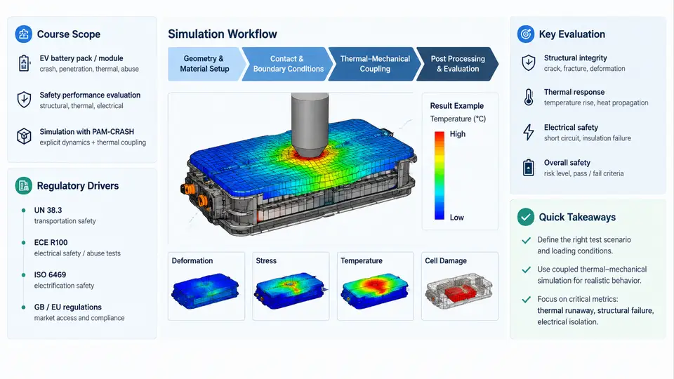
Electric-vehicle battery packs are large, heavy, energy-dense structures that must survive crash events without losing mechanical integrity, leaking coolant, or exposing cells to conditions that trigger thermal runaway. PAM-CRASH, part of the ESI Virtual Performance Solution (VPS) suite, is an explicit finite-element solver widely used in the automotive industry for exactly this class of problem. This chapter establishes what the course covers, why regulators and OEMs demand simulation evidence, and how a typical battery-pack crash simulation is structured from CAD to sign-off.
What This Course Covers
The course targets engineers who already understand basic explicit dynamics and want to apply PAM-CRASH specifically to traction battery safety. Across 30 chapters we move through four layers:
- Modeling layer — building the pack assembly: enclosure, module frames, busbars, cell stacks, cooling plates, and mounting points, with appropriate element types and material models.
- Load-case layer — regulatory and internal load cases: frontal, side pole, rear, bottom intrusion, and mechanical abuse such as crush and nail penetration.
- Assessment layer — extracting the metrics that matter: intrusion depth, cell deformation, connector strain, bolt forces, and clearance to live parts.
- Process layer — correlation with physical tests, model updating, and reporting for homologation.
The emphasis throughout is on decisions an analyst actually makes: which element formulation to use for a thin-walled enclosure, how to represent a cell stack without modeling every layer, and how to judge whether a result is trustworthy.
Why Simulation Is Mandatory, Not Optional
Battery safety is regulated through crash-test standards and, increasingly, through battery-specific mechanical abuse requirements. The most relevant drivers are:
| Driver | Region / Framework | What It Demands |
|---|---|---|
| FMVSS 305 / FMVSS 305a | United States | No electrolyte spillage, no battery displacement into the occupant compartment, and limits on post-crash electrical isolation after frontal and side barrier tests. |
| UN ECE R100 (Part II) | Europe / UN | Mechanical integrity and no fire or explosion after vibration, crush, and thermal shock sequences. |
| GB 38031 | China | Crush, vibration, and thermal propagation requirements, with defined acceptance windows. |
| OEM internal requirements | Global | Often stricter than regulation: no cell intrusion beyond a defined depth, no coolant leakage, and retention of high-voltage isolation resistance. |
Physical testing of a full pack is expensive and slow — a single side-pole test can consume a complete pack and weeks of preparation. Simulation lets engineers explore dozens of design variants before committing to hardware, and it produces the intrusion and force histories that regulators and internal safety boards expect to see alongside test data.
The Simulation Workflow at a Glance
A PAM-CRASH battery-pack study follows a repeatable pipeline. The diagram below shows the main stages and the feedback loops that connect them.
From CAD to Solver Deck: A Concrete Example
Consider a 400 V, 60 kWh pack with a steel enclosure and prismatic cells. A typical PAM-CRASH setup for a side-pole impact begins with geometry simplification: the full pack is reduced to the load-bearing structure plus a representative cell stack. The enclosure walls are meshed with four-node shell elements at roughly 5 mm target size in the impact zone and 10–15 mm elsewhere. Cell stacks are often represented as solid hexahedral blocks with homogenized orthotropic material properties rather than layered jelly-roll models, because the latter is prohibitively expensive for a full-pack run.
Material cards are then assigned. The enclosure uses an elastic-plastic steel model with strain-rate hardening — for example, a Cowper-Symonds formulation with C = 40 and p = 5 for mild steel, or a tabulated stress-strain curve from coupon tests. The cell stack uses a crushable foam model with a plateau stress around 2–5 MPa and densification strain near 0.6, calibrated from cell-level compression tests. Busbars and connectors are modeled with beam or shell elements and tied to the module frames.
Boundary conditions for a side-pole test follow the regulatory setup: the pack is mounted at its production attachment points, a rigid pole of 254 mm diameter is given an initial velocity of 32 km/h (or the OEM-specified value), and the pole is constrained to move along the lateral axis. Contact is defined between the pole and the enclosure, and between internal components that may collide during deformation.
Reading the Results
After the solve, the analyst extracts a small set of decisive metrics rather than browsing the entire field output. The most common are:
- Maximum intrusion depth into the cell stack — compared against the OEM limit, often 5–10 mm depending on cell chemistry and module design.
- Peak reaction force at the mounting points — checked against bolt shear and weld strength allowables.
- Cell strain or deformation — a proxy for internal short-circuit risk; values above a calibrated threshold trigger a design review.
- Clearance to live parts — ensuring no conductive path is created between the enclosure and high-voltage terminals.
If intrusion exceeds the limit, the usual first response is to add a reinforcement rib or increase wall thickness in the impact zone, then re-run. If the model is not yet correlated, the analyst may adjust the foam plateau stress or the failure strain of the enclosure steel within the range of coupon-test scatter before drawing conclusions.
What Comes Next
This chapter has framed the course: the regulatory pressure that makes simulation necessary, the four-layer structure of the work, and the end-to-end pipeline from CAD to assessment. The chapters that follow will open each stage in detail — starting with geometry preparation and meshing strategies specific to battery enclosures, then material calibration, contact definition, load-case setup, and finally correlation and reporting. By the end, you should be able to build, run, and defend a PAM-CRASH battery-pack model that stands up to both regulatory scrutiny and internal design reviews.