1. Occupant restraint system overview
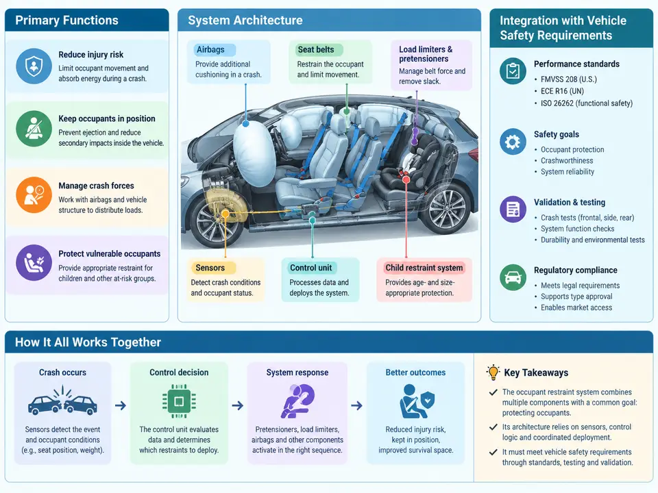
An occupant restraint system (ORS) is the coordinated set of structures, sensors, actuators, and energy-absorbing elements that manage the deceleration of vehicle occupants during a crash. Its purpose is not simply to "hold people in place" but to shape the occupant's kinematic response so that the forces transmitted to the body stay within tolerable limits while the occupant remains inside the survival space of the vehicle. Understanding the ORS as a system — rather than as a collection of parts — is the foundation for every downstream decision in restraint development: sensor calibration, airbag vent sizing, seatbelt load-limiter selection, and the validation matrix that proves compliance with regulatory and consumer safety requirements.
Primary Functions of the Restraint System
Four functions define what the ORS must accomplish, and each maps to measurable performance targets:
- Occupant containment and kinematics control. Keep the occupant within the vehicle's survival space and prevent hard contact with the interior (steering wheel, A-pillar, instrument panel). This is achieved through seatbelt geometry, pretensioning, and airbag deployment timing.
- Energy absorption and force limiting. Dissipate kinetic energy over a controlled distance and time. Belt load limiters, airbag vents, and crushable steering column elements convert peak force into a longer, lower-magnitude deceleration pulse.
- Load distribution. Spread restraint forces over large, tolerant body regions — the pelvis and rib cage for belts, the head and thorax for airbags — to avoid localized injury.
- Adaptivity and occupant discrimination. Adjust restraint severity to occupant size, seating position, and crash severity, so that a small occupant is not over-restrained and a large occupant is not under-restrained.
These functions are in tension. A stiffer belt reduces excursion but raises chest loading; an aggressive airbag protects a large occupant in a high-severity crash but can injure an out-of-position child. Restraint development is therefore an optimization problem constrained by regulation, occupant diversity, and packaging.
System Architecture
A modern ORS is organized into four architectural layers: sensing, decision, actuation, and structure. The sensing layer includes frontal and side accelerometers, pressure sensors in the doors, seat occupancy and weight sensors, buckle switches, and seat-position sensors. The decision layer is the Airbag Control Unit (ACU), which runs crash algorithms — typically a velocity-change (Δv) integration with severity thresholds and safing logic — and decides which restraint devices to fire and when. The actuation layer comprises pyrotechnic and mechanical devices: belt pretensioners, belt load limiters, frontal airbags (driver, passenger, knee), side airbags (thorax, pelvis), curtain airbags, and active seat elements. The structural layer includes the seat frame, steering column, instrument panel, and body structure that provide the reaction surface and survival space.
The ACU's firing decision is gated by a safing sensor — an independent accelerometer or mechanical switch that must also confirm the crash. This redundancy prevents inadvertent deployment from a single sensor fault. The deployment time budget is tight: for a 50 km/h frontal barrier impact, the decision must be made and the driver airbag inflated within roughly 30–50 ms of impact, because the occupant begins moving forward almost immediately.
Integration with Vehicle Safety Requirements
The ORS does not exist in isolation; it is validated against a hierarchy of requirements. At the top are regulatory mandates — FMVSS 208 (occupant crash protection), FMVSS 209/210 (belt assemblies and anchorages), FMVSS 214 (side impact), and UN R94/R95 in Europe. These define pass/fail criteria using instrumented Anthropomorphic Test Devices (ATDs, or "crash test dummies") and specify injury metrics such as Head Injury Criterion (HIC), chest deflection, and femur load. Below regulation sit consumer rating programs — US NCAP, Euro NCAP, and China NCAP — which are stricter and drive much of the real engineering effort. Finally, internal OEM requirements cover occupant diversity (5th-percentile female through 95th-percentile male), out-of-position (OOP) robustness, and durability.
Integration happens along three axes. Timing integration ensures the airbag is fully inflated before the occupant arrives but not so early that it is already deflating; this couples ACU calibration to occupant kinematics simulation. Force integration balances belt load limiting against airbag pressure so the combined chest loading stays below the injury threshold — a classic trade study. Packaging integration ensures the airbag module, its tear seam, and the deploying cushion have a clear path, and that the seat and body structure provide the reaction surfaces the restraint design assumes.
A Worked Integration Example
Consider a frontal 50 km/h rigid barrier development case for a mid-size sedan. The team must satisfy FMVSS 208 for both the 50th-percentile male and the 5th-percentile female. A representative workflow:
- Define the input pulse. Use the vehicle's measured barrier deceleration pulse (a 50 km/h impact producing roughly 30–40 g peak over ~100 ms) as the sled or CAE boundary condition.
- Set baseline restraint parameters. For example: pretensioner fire at 8 ms, belt load limiter at 3.5 kN, driver airbag vent diameter 30 mm, inflator output tuned to fill the cushion in ~25 ms.
- Run occupant simulation with a validated ATD model and extract HIC₁₅, chest deflection, and femur loads for both occupants.
- Check against targets. If the 5th-percentile female exceeds the chest deflection limit while the 50th-percentile male is comfortable, reduce the load limiter force or add a dual-stage inflator with a lower-output first stage for small occupants.
- Iterate and confirm that the change does not push the large occupant's excursion beyond the survival space or violate the airbag timing window.
Key Takeaways for Development
Treat the ORS as a closed-loop system: sensors observe, the ACU decides, actuators act, and structure reacts. Every requirement — regulatory, consumer, or internal — ultimately resolves into a constraint on one of these four layers. When a test fails, the diagnostic question is always the same: was the sensing decision correct, was the actuation timely and correctly sized, or did the structure fail to provide the assumed reaction? Answering that question systematically is what separates a compliant restraint system from a well-integrated one.