1. Define Occupant Restraint System Boundar
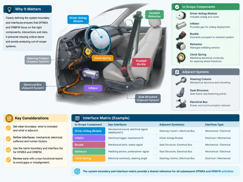
Why the Boundary Must Be Fixed Before Any Failure Analysis
A DFMEA on a driver airbag and seatbelt restraint system fails in a predictable way when the boundary is left implicit: the team starts listing failure modes, then discovers halfway through that half the causes belong to the steering column, the seat frame, or the vehicle electrical architecture. Ratings get assigned to items the restraint team does not own, interfaces are never analyzed by anyone, and the DRBFM later reopens questions that should have been settled on day one. The boundary and interface matrix is therefore not paperwork — it is the contract that determines what the DFMEA is allowed to say.
This case establishes that contract for a concrete system: the driver-side restraint chain consisting of the airbag module, inflator, clock spring, seatbelt retractor, buckle, and the wiring that ties them to the supplemental restraint system (SRS) controller. The deliverable is a boundary statement plus an interface matrix that classifies every adjacent system as either in scope, interface-controlled, or out of scope, with the specific exchange (mechanical, electrical, signal, or thermal) named for each crossing.
Step 1 — Anchor the Boundary on a Physical and Functional Cut
Use two complementary cuts and reconcile them. The physical cut follows the parts the restraint team releases: the module housing, cushion, inflator, retractor assembly, buckle assembly, clock spring, and the harness segment up to its first connector. The functional cut follows the restraint functions the system must perform: occupant positioning, energy absorption, load limiting, and deployment timing. Anything that performs a restraint function but is released by another group is an interface, not a scope item.
For the driver airbag and seatbelt system, the reconciled in-scope list is:
- Airbag module — housing, cushion, cover, mounting features, module connector.
- Inflator — pyrotechnic or hybrid gas generator, including its output port and mounting flange.
- Clock spring — the rotating conductor that carries the firing loop through the steering wheel rotation.
- Seatbelt retractor — spool, webbing, pretensioner, load limiter, locking mechanism.
- Buckle — latch mechanism, buckle pretensioner (if fitted), buckle switch.
- Restraint harness segment — from the module/buckle/retractor connectors to the first body-side connector.
Adjacent systems that must be named but not owned: steering column and wheel (module mounting, clock spring housing), seat structure (retractor and buckle anchorage, webbing routing), body electrical architecture and SRS controller (power, ground, firing loop, buckle switch signal), instrument panel and trim (deployment path), and the vehicle power supply (voltage during crash).
Step 2 — Classify Each Crossing by Exchange Type
An interface is only useful for DFMEA if it names what actually crosses it. Classify each crossing into one of four exchange types, because each type drives a different failure-mode family later:
| Exchange type | Example crossing in this system | DFMEA consequence family |
|---|---|---|
| Mechanical / structural | Module flange to steering wheel hub; retractor to seat frame | Loss of mounting stiffness, rattle, deployment path deviation |
| Electrical power | SRS controller to inflator firing loop; ground return | No-deploy, late deploy, unintended deploy |
| Signal / data | Buckle switch to SRS controller; seat position to occupancy logic | Misclassification of occupant state, suppression errors |
| Thermal / energy | Inflator gas output into cushion; cushion venting into cabin | Over-pressure, cushion rupture, burn injury |
Note that the clock spring is a special case: it is in scope, but it is simultaneously an interface carrier, because it transmits the firing loop across a rotating joint. Record it as an in-scope component and as an interface to the steering column rotation. This dual role is exactly the kind of ambiguity that causes interface failures to fall between teams.
Step 3 — Build the Interface Matrix
The matrix is a two-column contract: for each adjacent system, state the direction of exchange, the physical or logical carrier, and the owning team. The example below is the working matrix for this case; it is the artifact that anchors every later DFMEA line item.
| Adjacent system | Direction | Exchange / carrier | Owner | Classification |
|---|---|---|---|---|
| Steering column & wheel | Restraint → Column | Module mounting torque, clock spring housing fit | Chassis / Steering | Interface-controlled |
| Seat structure | Restraint → Seat | Retractor and buckle anchorage, webbing routing | Seat Engineering | Interface-controlled |
| SRS controller | Bidirectional | Firing loop, buckle switch signal, ground | Electrical / SRS | Interface-controlled |
| Body electrical architecture | Vehicle → Restraint | Power supply, connector keying, EMC environment | Electrical | Out of scope (constraint only) |
| Instrument panel / trim | Restraint → IP | Deployment path, tear seam, clearance | Interior | Interface-controlled |
| Vehicle power supply | Vehicle → Restraint | Voltage during crash, back-up power | Electrical | Out of scope (constraint only) |
Two rules keep the matrix honest. First, every row must have exactly one owner for the interface itself — usually the restraint team, because the restraint team is the one that must prove the interface works. Second, "out of scope" rows are still recorded, because a constraint (voltage, EMC, connector keying) can still be a cause in the DFMEA even when the item is not owned.
Step 4 — Verify the Boundary Against a Deployment Scenario
A boundary is only correct if it survives a walk-through of a real event. Trace a frontal crash at 50 km/h: the SRS controller decides to fire, current crosses the body harness to the clock spring, the clock spring carries it to the module connector, the inflator fires, gas fills the cushion, the cushion tears the cover and deploys through the IP/steering wheel opening, the retractor pretensioner fires and the load limiter pays out webbing, and the buckle holds the latch. At each arrow, ask: who owns this crossing, and is it in the matrix? If an arrow has no owner, the boundary is incomplete.
The SVG below shows this chain with the scope boundary drawn as a closed region, so the in-scope components sit inside and every crossing is labeled with its exchange type and owner.
Step 5 — Freeze the Boundary and Hand It to DFMEA
Once the matrix is agreed, freeze it with three checks before the first DFMEA line item is written. First, every in-scope component must appear in at least one interface row or be explicitly declared self-contained. Second, every interface row must name a carrier (torque, connector, signal, gas path) — a row that says only "mechanical interface" is not yet usable. Third, every out-of-scope row must state the constraint it imposes, because that constraint becomes a cause in the DFMEA even though the item is not owned.
A practical verification is to hand the matrix to a reviewer who was not in the workshop and ask them to trace the 50 km/h frontal crash chain using only the matrix. If they can name the owner at every arrow, the boundary is complete. If they find an arrow with no owner — typically the clock spring rotation, the buckle switch signal, or the ground return — the matrix is not yet frozen.
Deliverable — Boundary and Interface Matrix (Fill-In Template)
The table below is the working template for this case. Fill one row per crossing; the classification column must be one of in scope, interface-controlled, or out of scope (constraint).
| # | Adjacent system | Direction | Exchange / carrier | Owner | Classification | Constraint imposed |
|---|---|---|---|---|---|---|
| 1 | Steering column & wheel | Restraint → Column | Module mounting torque, clock spring housing fit | Chassis / Steering | Interface-controlled | Mounting stiffness, rotation range |
| 2 | Seat structure | Restraint → Seat | Retractor/buckle anchorage, webbing routing | Seat Engineering | Interface-controlled | Anchor strength, routing clearance |
| 3 | SRS controller | Bidirectional | Firing loop, buckle switch signal, ground | Electrical / SRS | Interface-controlled | Loop resistance, signal timing |
| 4 | IP / trim | Restraint → IP | Deployment path, tear seam, clearance | Interior | Interface-controlled | Opening force, clearance envelope |
| 5 | Body electrical | Vehicle → Restraint | Power, EMC, connector keying | Electrical | Out of scope (constraint) | Voltage range, EMC class |
| 6 | Vehicle power supply | Vehicle → Restraint | Crash voltage, back-up power | Electrical | Out of scope (constraint) | Minimum firing voltage |
With this matrix frozen, every subsequent DFMEA failure mode can be traced to a defined function and a named interface, and the DRBFM can focus on change-affected crossings rather than re-litigating the boundary.