1. Course overview
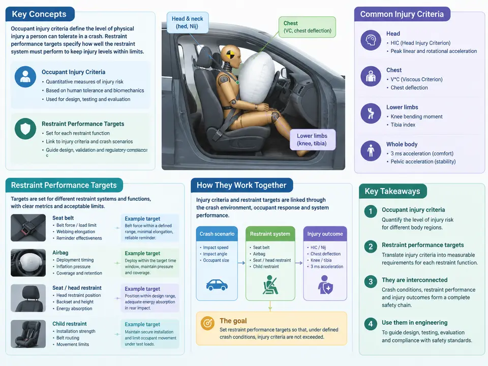
Vehicle safety engineering is fundamentally a chain of evidence: a crash event produces a kinematic and kinetic environment, the restraint system shapes how the occupant interacts with that environment, and the resulting loads on the human body determine whether injury occurs. This course sits at the two ends of that chain — the injury criteria that quantify what the body can tolerate, and the restraint performance targets that translate those tolerances into engineering specifications a design team can actually design, test, and validate against.
Most engineers entering this field encounter injury criteria as a list of acronyms — HIC, BrIC, Nij, a3ms, chest deflection, femur force — and restraint targets as numbers in a requirements document. The gap between those two views is where real engineering happens. A target such as "HIC15 ≤ 700 at 56 km/h frontal barrier" is not an arbitrary threshold; it is the output of a chain of reasoning that begins with tissue-level tolerance, passes through anthropometry and biomechanical scaling, is filtered through regulatory and consumer-rating requirements, and is finally allocated to subsystem performance with margin for production variation. This chapter establishes that chain and the vocabulary used throughout the course.
The Two Halves of the Problem
Injury criteria are quantitative functions of measurable physical quantities — acceleration, force, moment, deflection, pressure — that correlate with a defined injury outcome at a defined severity level. They exist because the directly relevant quantity, actual tissue damage, cannot be measured in a crash test. Instead, we measure what an Anthropomorphic Test Device (ATD, or "dummy") or a human body model (HBM) can report, and rely on established correlations between those measurements and real-world injury risk.
Three properties of an injury criterion matter for target setting. First, its physical basis: is it an acceleration-based criterion (HIC), a force/moment-based criterion (Nij, neck tension), a deformation-based criterion (chest deflection), or a combined kinematic criterion (BrIC, which uses angular velocity)? Second, its severity reference: most criteria are defined at a specific AIS (Abbreviated Injury Scale) level, typically AIS 2 or AIS 3, and a criterion value quoted without its AIS reference is incomplete. Third, its statistical nature: tolerance is a distribution, not a point. The value used in regulation is usually a conservative percentile of that distribution, not the mean.
Restraint performance targets are the engineering-side counterpart. They specify what the restraint system — belt geometry, pretensioner, load limiter, airbag volume and venting, seat structure — must achieve in a defined test condition so that the occupant's measured response stays below the injury criteria with adequate margin. Targets are therefore always conditional: they belong to a test matrix (impact mode, speed, barrier type, occupant size, seating position, belt usage), and they carry tolerances and statistical confidence requirements.
How the Course Is Structured
The course proceeds from biomechanics to specification to verification. Early chapters build the injury-criteria foundation: head and brain criteria (HIC, BrIC, and their limitations), neck and spine (Nij, tension/compression, flexion/extension moments), thorax (deflection, viscous criterion, a3ms), and the abdomen, pelvis, and lower extremities. Each criterion is presented with its measurement location, its reference AIS level, and the practical conditions under which it loses validity — for example, HIC's known insensitivity to rotational loading, which is precisely why BrIC was introduced.
The middle portion converts criteria into targets. This includes the regulatory landscape (FMVSS 208, FMVSS 214, ECE R94/R95, and consumer programs such as Euro NCAP and C-NCAP), the difference between pass/fail regulatory limits and rating thresholds, and the systematic allocation of occupant-level targets down to subsystem and component requirements. A recurring theme is margin management: a design that exactly meets a regulatory limit in one nominal test will fail in production, so targets are set with explicit allowance for test-to-test variation, ATD biofidelity uncertainty, and manufacturing tolerance.
The final portion addresses execution: sled and full-vehicle test setup, signal conditioning and filtering (CFC filters per SAE J211), data reduction, and the judgment of whether a result demonstrates compliance. This is where many otherwise sound programs fail — not in the design, but in the measurement chain or in the interpretation of a marginal result.
The Target-Setting Chain, Visualized
The diagram below shows how a tissue-level tolerance becomes a validated restraint specification. Read it left to right: each stage narrows the requirement and adds engineering specificity, while the feedback path on the bottom shows that a failed validation does not automatically mean redesigning the restraint — it may indicate that the target itself was set without sufficient margin or against the wrong criterion.
A Worked Illustration of the Chain
Consider a frontal 56 km/h rigid barrier test with a 50th-percentile male ATD in the driver position. The regulatory requirement (FMVSS 208) sets HIC15 ≤ 700 and chest deflection ≤ 63 mm for this configuration. A program targeting a five-star consumer rating will not design to those limits; it will set internal occupant targets well below them — for instance HIC15 ≤ 500 and chest deflection ≤ 45 mm — because rating bands are tighter than regulatory limits and because the design must hold across the full build population, not just the nominal test.
Those occupant targets then allocate to hardware. Head excursion and HIC are governed jointly by belt force limiting and airbag pressure; a load limiter that is too aggressive reduces chest loading but allows greater forward excursion and a higher head impact velocity. The engineer therefore works with a coupled pair of targets — for example, belt load limit around 3.5–4.5 kN with a vented 60 L driver airbag — and confirms the pairing in sled testing before committing to hardware. The specific numbers here are illustrative of typical practice, not measured results; the point is that the target is a pair or set of coupled constraints, not a single scalar.
What You Should Be Able to Do After This Course
- State the physical basis, measurement channel, and AIS reference level for the principal injury criteria used in frontal, side, and rear impact.
- Distinguish regulatory pass/fail limits from consumer-rating thresholds and explain why internal targets are set below both.
- Construct a defensible occupant-level target from a criterion, a requirement, and an explicit margin budget.
- Allocate occupant targets to restraint subsystems and recognize the coupling between them (load limiter vs. excursion, airbag pressure vs. chest loading).
- Reduce and interpret test data correctly, including filter class, channel sign convention, and the treatment of marginal results.
The remainder of the course builds each link of this chain in detail, beginning with the biomechanical basis of the head and brain criteria, where the distinction between translational and rotational loading first becomes engineering-relevant.