1. DVP&R fundamentals for crashworthiness
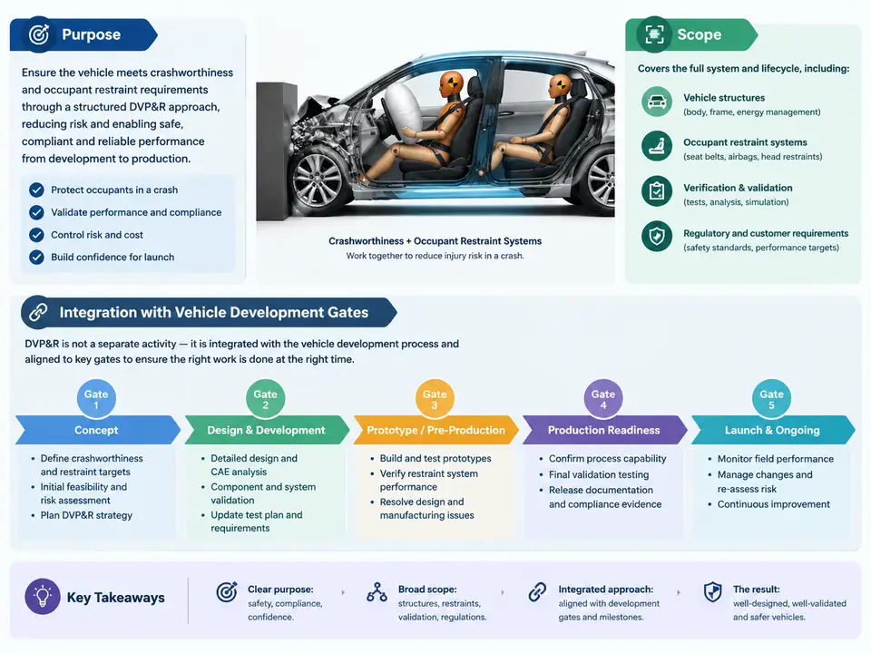
A Design Verification Plan and Report (DVP&R) is the controlled document that proves a vehicle's crashworthiness and occupant restraint performance meet every requirement it was designed against. In the crash and restraint domain, it is not a compliance formality completed near Job 1; it is the engineering contract between the requirements baseline, the physical and analytical evidence, and the gate decisions that release the vehicle to the next phase of development. This chapter establishes what a crashworthiness DVP&R contains, how its scope is bounded, and how it must be structured so that evidence arrives in time to support each vehicle development gate.
Purpose: From Requirement to Signed Evidence
Crashworthiness performance is defined by a set of requirements that originate from regulation, consumer rating programs, internal brand targets, and program-specific attribute targets. Examples include FMVSS 208 occupant protection, FMVSS 214 side impact, FMVSS 216a roof crush, FMVSS 301 fuel system integrity, UN R94/R95 frontal and side impact, and consumer programs such as US NCAP and Euro NCAP. Each requirement decomposes into measurable acceptance criteria: HIC36 or HIC15 limits, chest deflection in millimetres, femur axial force in kN, neck Nij, intrusion limits at defined structural reference points, fuel leakage rate, and door latch/unlatch behaviour.
The DVP&R exists to answer three questions for every one of those criteria: what will be verified, how it will be verified (test, CAE, or inspection), and what evidence proves it passed. A well-formed DVP&R line is traceable in both directions — upward to the requirement identifier and downward to the test report, simulation correlation package, or inspection record. Without that traceability, a gate review cannot distinguish "not yet tested" from "tested and failed" from "tested but the build level was wrong."
Scope: What Belongs in a Crashworthiness DVP&R
Scope is bounded by the vehicle architecture, the market set, and the restraint system content. A practical scoping exercise enumerates the following dimensions before any line is written:
- Impact modes: full frontal rigid barrier, offset deformable barrier (ODB), oblique moving deformable barrier, side MDB, pole side impact, rear impact, roof crush, and pedestrian/cyclist protection where applicable.
- Occupant positions: driver, front passenger, second-row outboard and centre, third row where fitted, plus out-of-position (OOP) cases for airbag deployment.
- Restraint content: seat belts with pretensioners and load limiters, frontal airbags, side airbags, curtain airbags, knee bolsters, seats and head restraints, child restraint anchorage (ISOFIX/LATCH, top tether).
- Build levels: mule, prototype A/B/C, pre-production, and production-representative vehicles, each with a defined configuration matrix.
- Markets and regulatory variants: left-hand and right-hand drive, different bumper and structure content, regional restraint calibration differences.
Scope also has an explicit exclusion list. If a variant is not in the DVP&R, it is not verified, and the gate decision must record that gap. Writing the exclusion list down is as important as writing the inclusion list, because it prevents the common failure mode where a late market addition is assumed to be covered by a "similar" test.
Anatomy of a Verification Line
Each line in the DVP&R carries a consistent field set. The following example shows a representative frontal occupant protection line; the values are illustrative and intended to show structure, not measured results.
| Field | Example content |
|---|---|
| Requirement ID | REQ-CR-FR-014 — Driver HIC15 ≤ 700 in 56 km/h full frontal rigid barrier |
| Verification method | Physical sled + full vehicle test; CAE correlation package |
| Acceptance criterion | HIC15 ≤ 700; peak chest deflection ≤ 42 mm; femur force ≤ 6.0 kN per leg |
| Test object / build level | Prototype B, driver restraint calibration CAL-B2, 50th percentile Hybrid III |
| Facility / standard | Accredited crash lab; FMVSS 208 test procedure, internal TP-CR-021 |
| Planned gate | Gate 3 — Prototype B verification complete |
| Evidence reference | Test report TR-CR-208-0117; CAE correlation report CAE-COR-0042 |
| Status | Open / Pass / Fail / Conditional |
Two fields deserve emphasis. First, the build level must be pinned to a configuration identifier, not just "prototype." A restraint calibration change between prototype builds can move HIC by tens of points, so a pass on an earlier calibration does not close a line for a later one. Second, the evidence reference must be a real, retrievable artefact. During gate reviews, the reviewer should be able to open the report and confirm the test configuration matches the DVP&R line.
Integration with Vehicle Development Gates
Vehicle programs are structured around gates — typically concept freeze, design freeze, prototype A/B/C builds, tooling kick-off, and start of production. The DVP&R must be phased so that the right evidence exists at the right gate. A common and workable phasing is:
- Concept gate: requirements baseline frozen; DVP&R skeleton with all requirement IDs and planned methods; CAE-only evidence acceptable for architecture-level feasibility.
- Design freeze: CAE correlation against component and sled tests; restraint system layout verified analytically; physical test plan scheduled with facility bookings.
- Prototype B gate: full vehicle crash tests for primary load cases; occupant criteria demonstrated on representative build; open failures have documented containment and re-test plans.
- Pre-production gate: all regulatory and consumer-program lines closed or conditionally closed with production-representative evidence; CAE models correlated within agreed tolerance.
- Start of production: DVP&R signed off; residual risks recorded; any conditional closures carry a monitoring plan.
The critical discipline is that a gate cannot be passed on the strength of a plan. If a line is still "planned" at the gate where it was due, the gate decision must explicitly accept that risk or hold. This is where DVP&R integration with program management becomes real: the DVP&R status roll-up feeds the gate review pack, and the gate review pack drives the program decision.
Making the DVP&R Operable
A DVP&R that lives only in a spreadsheet reviewed at gates will drift. To keep it operable, three practices matter. First, assign each line an owner — typically the restraint engineer, body structure engineer, or CAE lead — who is accountable for the evidence, not just the test booking. Second, review status weekly against the gate calendar, not monthly, because crash test facilities have long lead times and a slipped booking can push a gate. Third, treat CAE and test as a single evidence chain: a CAE result that has not been correlated to a physical test at the relevant build level is supporting evidence, not closure evidence.
A practical weekly review looks at four numbers: lines due before the next gate, lines with evidence in review, lines failed with containment open, and lines whose build level no longer matches the current prototype configuration. The last category is the most frequently missed and the most damaging, because it produces a gate pack that looks complete while the evidence no longer represents the vehicle being released.
What Good Looks Like at the First Gate
By the concept gate, a credible crashworthiness DVP&R has every requirement identified, every line assigned a method and an owner, and a phasing plan that places each evidence type before the gate that depends on it. It will not yet have results, and it should not pretend to. What it must have is completeness of scope, clarity of acceptance criteria, and a gate-by-gate schedule that the program can resource. That foundation is what allows later gates to be decided on evidence rather than on optimism.