1. DFMEA fundamentals for CAE
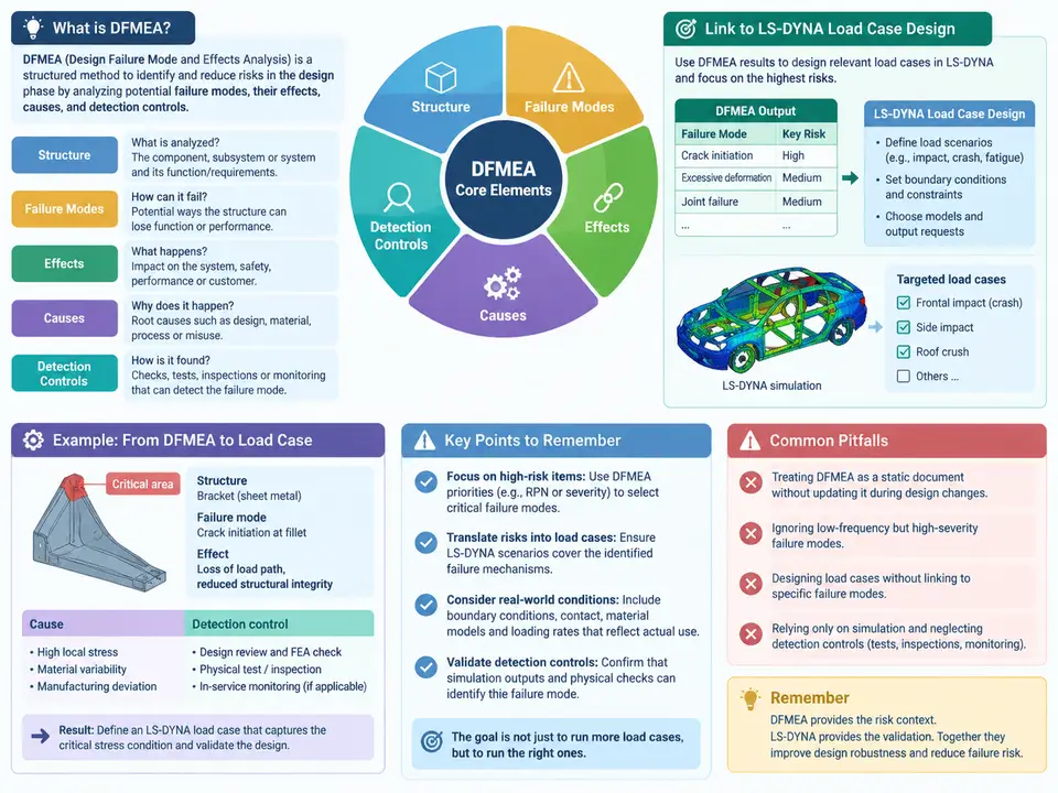
Design Failure Mode and Effects Analysis (DFMEA) is a structured risk-assessment method that asks a deceptively simple question: for each way a design can fail, how bad is the consequence, how likely is the cause, and how reliably can we catch it before it reaches the customer? In a CAE-driven development process, DFMEA and LS-DYNA load case design are not parallel activities — they are coupled. The DFMEA defines what must be simulated and why; the LS-DYNA load cases provide the quantitative evidence that either confirms or refutes the assumed failure behavior. When this coupling is weak, teams produce impressive-looking simulations that answer the wrong questions, and DFMEA rows that cite "CAE verified" without a traceable load case behind them.
This chapter establishes the vocabulary and structure you will use throughout the course. The goal is not to memorize a form, but to understand how each DFMEA column maps onto a concrete decision in load case design: which model, which boundary conditions, which output metric, and which acceptance threshold.
The DFMEA Structure and Its CAE Interpretation
A DFMEA worksheet is organized around a failure chain: Item/Function → Failure Mode → Effect(s) → Severity → Cause(s) → Occurrence → Prevention Control → Detection Control → Detection → Risk metric → Recommended Action. For CAE engineers, the critical insight is that this chain is also a simulation specification chain. The function tells you what the structure is supposed to do; the failure mode tells you what physical response to look for; the effect tells you which output quantity matters (stress, intrusion, acceleration, residual deformation); the cause tells you which design or load parameter to vary; and the detection control tells you which simulation result, test, or inspection will reveal the failure.
Consider a simplified but realistic example used throughout this chapter: a front bumper beam assembly in a passenger car, made of DP590 steel with a 1.8 mm wall thickness, bolted to the front longitudinal rails. Its function is to absorb low-speed impact energy (a 16 km/h RCAR-style barrier impact) and to protect the cooling module and hood from damage. This function statement is already a load case specification in disguise: it names the load (barrier impact at a defined velocity), the response of interest (energy absorption and deformation), and the protected objects (cooling module, hood).
Failure Modes: From Function to Physical Response
A failure mode is the manner in which a component fails to perform its function. For the bumper beam, plausible failure modes include:
- Excessive permanent deformation — the beam does not spring back, leaving a visible dent and reducing subsequent energy absorption capacity.
- Fracture at the bolt holes — stress concentration at the mounting points causes tearing under impact.
- Insufficient energy absorption — the beam buckles locally instead of forming stable plastic hinges, so too much energy is transmitted to the rails.
- Detachment from the rails — bolt or weld failure allows the beam to separate, transferring load directly to the cooling module.
Each of these maps to a distinct LS-DYNA modeling concern. Excessive permanent deformation requires an accurate elastic-plastic material model with proper unloading behavior (e.g., *MAT_PIECEWISE_LINEAR_PLASTICITY with a calibrated hardening curve). Fracture at bolt holes requires either a strain-based failure criterion or a damage model such as *MAT_ADD_EROSION or GISSMO, plus a mesh fine enough to resolve the stress gradient around the hole. Insufficient energy absorption requires careful control of hourglass energy and shell element formulation, because a poorly controlled simulation can artificially stiffen or soften the buckling response. Detachment requires explicit modeling of the connection — spot welds with *MAT_SPOTWELD or tied contacts — and a way to detect connection failure in the output.
Effects and Severity: What the Customer and the Program Care About
Effects describe the consequence of the failure mode at the vehicle, system, or customer level. For the bumper beam, "fracture at bolt holes" might produce the effect "beam detaches, cooling module perforated, vehicle undrivable" — a severe effect. Severity (S) is rated on a 1–10 scale, where 10 represents a safety-related failure without warning and 1 represents no discernible effect. The rating is assigned to the effect, not the failure mode, and it is independent of how likely the failure is.
In CAE terms, severity drives the acceptance threshold and the required fidelity. A severity-9 effect (potential safety consequence) demands a load case with validated material data, mesh convergence study, and correlation to physical test. A severity-3 effect (cosmetic dent) may be adequately assessed with a coarser model and a simpler material law. This is the first place where DFMEA prevents wasted effort: it tells you where simulation accuracy is worth paying for.
Causes, Occurrence, and Prevention Controls
Causes are the specific design or process conditions that produce the failure mode. For "fracture at bolt holes," causes might include: insufficient edge distance from hole center to beam flange, material with lower-than-specified elongation, or high bolt preload combined with impact loading. Occurrence (O) rates the likelihood that a given cause will occur, again on a 1–10 scale, ideally anchored to field data, test history, or validated simulation evidence rather than intuition.
Prevention controls are actions that reduce the likelihood of the cause. In a CAE context, prevention controls are often design and verification activities performed before the load case: a design guideline requiring edge distance ≥ 2.5× hole diameter, a material specification with a minimum elongation, or a coupon test program that establishes the actual hardening curve. These controls are "prevention" because they act on the cause, not on the detection of the failure.
Detection Controls: The Bridge to LS-DYNA
Detection controls describe how the failure mode will be found if it occurs. This is where DFMEA and LS-DYNA load case design meet most directly. A detection control for "fracture at bolt holes" might read: "LS-DYNA frontal impact load case at 16 km/h; output effective plastic strain at bolt-hole elements; flag if strain exceeds the calibrated failure strain of 0.28." That sentence contains a complete simulation specification: load case, output request, location, metric, and threshold.
Detection (D) rates the ability of the control to detect the failure before it reaches the customer, on a 1–10 scale where 1 means certain detection and 10 means no detection. A simulation-based detection control is only as good as its correlation: if the model has never been validated against a physical test for this failure mode, the detection rating should reflect that uncertainty. This is a common failure in practice — teams assign D=2 because "we ran a simulation," without asking whether the simulation was capable of predicting the specific failure mode.
Risk Metrics and the Action Threshold
The traditional Risk Priority Number (RPN = S × O × D) is widely used but has well-known weaknesses: it treats the three factors as interchangeable, so a severity-9 failure can be masked by low occurrence and detection ratings. Many organizations now use an Action Priority (AP) table — High / Medium / Low — that prioritizes severity first, then occurrence and detection. For CAE work, the practical rule is: any failure mode with severity ≥ 8 requires a validated load case and a documented correlation, regardless of RPN.
The figure below shows how a single DFMEA row for the bumper beam translates into a load case specification, and how the risk rating feeds back into the required simulation fidelity.
Putting It to Work: A Minimal DFMEA-to-Load-Case Checklist
The following checklist is a compact, directly usable artifact for the first pass of any new component. It is deliberately short — the full worksheet lives in the DFMEA file, but this checklist ensures that no load case is designed without a traceable DFMEA origin.
| Check | Question to Answer | Typical Evidence |
|---|---|---|
| Function traceability | Does each load case trace to a DFMEA function statement? | Function ID in load case report header |
| Failure mode coverage | Does the output metric directly observe the stated failure mode? | Metric definition (e.g., ε_p at hole) and location |
| Severity-driven fidelity | Is simulation fidelity commensurate with severity? | Mesh convergence, material validation level |
| Threshold justification | Is the acceptance threshold derived from test or validated material data? | Coupon test report, correlation plot |
| Detection honesty | Does the D rating reflect actual correlation status? | Correlation report reference or "unvalidated" flag |
| Feedback loop | Is there a defined action if the threshold is exceeded? | Design change request or re-run trigger |
Two practical notes on using this checklist. First, the "detection honesty" row is the one most often skipped. A team that has run a beautiful LS-DYNA model but never correlated it against a physical test for the specific failure mode should rate D conservatively (typically 6–8), not 2–3. The DFMEA is a risk document, not a marketing document. Second, the feedback loop must be explicit: if the simulation predicts ε_p,max = 0.34 against a threshold of 0.28, the correct response is not to adjust the threshold but to revise the design (increase edge distance, change material grade) and re-run — and then update the occurrence rating in the DFMEA to reflect the new design state.
Common Pitfalls in CAE-Oriented DFMEA
Failure modes written as simulation outputs. "Von Mises stress exceeds yield" is not a failure mode; it is a result. The failure mode is "beam yields permanently, leaving residual deformation." The distinction matters because the effect and severity attach to the physical consequence, not the numerical result.
Detection controls without thresholds. "Review stress plots" is not a detection control. It has no pass/fail criterion and therefore cannot detect anything reliably. Every detection control should name the metric, the location, and the threshold.
Occurrence ratings disconnected from simulation evidence. If a validated load case shows the design has large margin, occurrence should drop — but only if the load case is correlated. An uncorrelated simulation is weak evidence for occurrence reduction.
Severity inflation or deflation. Severity is about the consequence to the customer or to safety, not about how hard the simulation is. A cosmetic dent on a visible surface may warrant S=5–6 because of customer perception, while an internal bracket fracture with no functional consequence may be S=3–4 even though it is harder to simulate.
With this foundation in place, the next step is to translate these DFMEA rows into a formal load case matrix — defining load case IDs, boundary conditions, output requests, and acceptance criteria in a form that can be executed repeatably in LS-DYNA and audited against the DFMEA. That translation is the subject of the chapters that follow.