1. Course overview
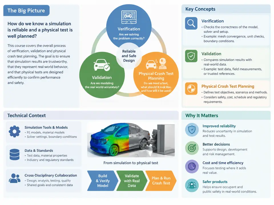
CAE Verification, Validation, and Physical Crash Test Planning sits at the intersection of numerical simulation and experimental testing. It is the discipline that answers a deceptively simple question: how do we know that a computer model of a crash event is trustworthy enough to make engineering decisions with? In vehicle safety development, those decisions include whether a restraint system will protect an occupant, whether a body structure will absorb energy as intended, and whether a design will meet regulatory and consumer-rating requirements before a single physical prototype is built.
This opening chapter establishes the vocabulary, the scope, and the technical context that the remaining 29 chapters build upon. It is deliberately conceptual, but it is not abstract: every term introduced here maps directly to artifacts, activities, and decisions that appear later in the course.
Why Verification and Validation Are Separate Activities
The terms verification and validation are frequently used interchangeably in casual engineering conversation, but they answer different questions and are governed by different evidence.
- Verification asks: Are we solving the equations correctly? It is a mathematics-and-numerics activity. Typical evidence includes mesh convergence studies, energy balance checks, comparison against analytical solutions, and code-to-code benchmarking. Verification does not require a physical test.
- Validation asks: Are we solving the right equations for this physical reality? It is an empirical activity. It requires a physical experiment, a quantified comparison between simulation and measurement, and an explicit statement of the conditions under which the model is considered adequate.
A model can be verified but not validated (numerically clean but physically wrong), or validated within a narrow regime but not verified (matches one test by coincidence or calibration). Both failure modes are common in crash simulation, which is why the course treats them as parallel, independently evidenced tracks.
The Crash-Specific Technical Context
Crash simulation is an unusually demanding application of explicit finite element analysis. The relevant physics include large deformation, strain-rate-dependent material behavior, contact and self-contact, rupture and failure, and highly nonlinear boundary conditions. The numerical scheme is typically explicit time integration with a stable time step governed by the smallest element and the wave speed:
Δt_crit ≈ L_min / c,   c = sqrt(E / ρ)

Example (steel, E = 210 GPa, ρ = 7850 kg/m³):
c ≈ sqrt(210e9 / 7850) ≈ 5172 m/s
For L_min = 5 mm:  Δt_crit ≈ 0.005 / 5172 ≈ 9.7e-7 s ≈ 0.97 µs
This single relationship explains much of the discipline's character. A 150 ms frontal impact at a ~1 µs step requires on the order of 150,000 time steps; mass scaling, element quality, and hourglass control therefore become validation-relevant decisions, not mere modeling preferences. If mass scaling adds non-physical inertia, the model may still "run," but its validation status is compromised. The course will return to this tension repeatedly.
Where Physical Testing Fits
Physical crash tests are expensive, destructive, and schedule-critical. A single full-vehicle frontal barrier test can consume a complete prototype and weeks of lead time. Their role in a verification-and-validation program is therefore twofold: they provide the empirical anchor for model validation, and they provide the final confirmation that the design meets its targets. Test planning is the bridge — it determines what is measured, at what resolution, under what boundary conditions, and with what instrumentation, so that the resulting data are actually usable for correlation.
A poorly planned test produces data that cannot validate anything: channels saturated, mounting stiffness undocumented, or impact conditions outside the model's intended regime. Conversely, a well-planned test with documented boundary conditions, calibrated instrumentation, and synchronized high-speed video becomes a reusable validation asset across multiple design iterations.
The End-to-End Workflow
The diagram below shows how the major activities connect. Note that verification and validation are not sequential gates but parallel evidence streams that converge on a single decision: is the model adequate for its intended use?
Key Concepts and Their Relationships
Several concepts recur throughout the course and are worth defining precisely at the outset.
| Concept | Definition | Typical Evidence |
|---|---|---|
| Intended use | The specific engineering decisions the model is meant to support | Documented use-case statement |
| Verification | Demonstration that the numerical solution is accurate for the governing equations | Convergence study, energy balance |
| Validation | Quantified agreement between model and physical measurement within a defined regime | Correlation metrics, test data |
| Uncertainty quantification | Characterization of variability and error in both model and test | Sensitivity study, tolerance bands |
| Correlation | The process of comparing simulation and test time histories and judging agreement | Overlay plots, objective rating scores |
| Boundary condition fidelity | How faithfully the test setup reproduces the modeled constraints and loading | Fixture stiffness, impactor speed tolerance |
The concept of intended use deserves emphasis. Validation is never absolute; it is always relative to a purpose. A model validated for a 50 km/h full frontal rigid barrier impact may be entirely inadequate for a 32 km/h oblique pole impact. The course therefore treats every validation claim as carrying an implicit scope statement: validated for these conditions, for these outputs, to this accuracy.
What the Course Covers
The 30 chapters are organized into four connected arcs. The first arc (Chapters 1–8) establishes foundations: verification and validation concepts, the crash simulation numerical context, material and contact modeling implications, and the structure of a validation program. The second arc (Chapters 9–16) develops physical test planning in depth — objectives, instrumentation selection and range sizing, fixture and boundary condition design, data acquisition, and test documentation. The third arc (Chapters 17–24) addresses correlation methodology: signal processing, objective rating metrics, uncertainty and sensitivity analysis, and model updating. The final arc (Chapters 25–30) integrates these into program-level practice, including regulatory and consumer-rating contexts, decision-making under uncertainty, and reporting.
Throughout, the course uses worked examples with clearly labeled assumed parameters. Where a numerical value appears — a sensor range, a correlation score, a time step — it is presented as a teaching example unless explicitly identified as a standard requirement. This distinction matters: the goal is to build judgment about how such values are chosen and defended, not to memorize specific numbers.
Practical Framing: A First Decision
Consider a concrete opening scenario that recurs in later chapters. A team must decide whether an existing full-vehicle model, previously validated for a 50 km/h frontal impact, can be used to predict occupant response in a 64 km/h offset deformable barrier (ODB) test. The verification track is already satisfied — the model runs stably and conserves energy. The validation question is whether the existing empirical evidence extends to the new loading regime. Answering it requires: identifying which outputs matter for the decision (occupant chest acceleration, intrusion), checking whether the test plan for the ODB test will produce comparable channels at comparable bandwidth, and defining an acceptance criterion before seeing the data. This is the discipline the course teaches — not just running simulations and tests, but constructing the evidentiary chain that makes their results defensible.
With this scope established, the following chapters move from concepts to the numerical and experimental detail that makes each link in that chain concrete.