1. Airbag System DFMEA Scope and Boundary D
Why Scope and Boundary Definition Comes First
A DFMEA is only as trustworthy as the boundary it is built on. For a driver airbag module, the temptation is to start listing failure modes immediately — "no deployment," "late deployment," "inadvertent deployment" — and then argue about severity. That order is backwards. Before any failure mode can be rated, the team must agree on three things: what is inside the analyzed item, what is outside but connected to it, and which functions the item is expected to perform. Without that agreement, two engineers will rate the same failure mode against different assumptions, and the resulting Action Priority numbers become non-comparable.
This case establishes the DFMEA scope for a driver airbag module in a passenger-car steering-wheel assembly. The deliverable is a boundary and interface definition that a cross-functional team can sign off on, plus the function list that the subsequent failure-mode analysis (Cases 2 and 3) will consume directly.
Establishing the System Boundary
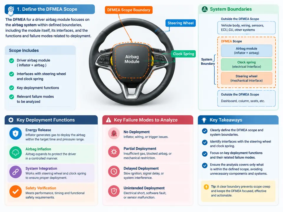
The analyzed item is the driver airbag module: the inflator, the folded cushion and its retention, the module housing and cover (including the tear seam), the module-to-steering-wheel mounting, and the internal wiring harness up to the connector. Everything that generates, contains, or releases the deployment energy belongs inside the boundary.
Three categories sit deliberately outside the boundary but must be documented as interfaces, because a DFMEA that silently absorbs them will either double-count failure modes or miss them entirely:
- Steering wheel and column — the module is bolted to the wheel armature; the wheel transmits driver input and carries the horn circuit. The module's reaction surface and the cover's tear-seam release are mechanically coupled to the wheel's geometry.
- Clock spring (spiral cable) — supplies the squib firing circuit and horn ground across the rotating column. It is a separate item with its own DFMEA, but its continuity and pinout are a hard interface for the airbag module.
- Restraints control module (RCM) and vehicle harness — the RCM decides deployment and delivers the firing current; the harness carries it. The airbag module's responsibility begins at its own connector.
A useful discipline is to state the boundary as a sentence the whole team can repeat: "The driver airbag module includes the inflator, cushion, housing, cover, and internal harness up to and including the module connector; it excludes the clock spring, steering wheel armature, RCM, and vehicle harness, which are treated as interface items." If a proposed failure mode cannot be assigned to exactly one side of that sentence, the boundary is still ambiguous.
Interface Definition: The Part That Gets Skipped
Interfaces are where airbag DFMEAs most often fail in practice, because the failure is shared between two items and each team assumes the other owns it. For the driver module, four interfaces deserve explicit entries with defined characteristics:
| Interface | Physical / functional characteristic | Owning item | What the module DFMEA must assume |
|---|---|---|---|
| Module ↔ steering wheel armature | Mounting bolt pattern, torque, seating plane, horn contact | Steering wheel | Armature is rigid and correctly torqued; horn circuit continuity is provided |
| Module ↔ clock spring | Squib circuit pins, loop resistance, current capacity | Clock spring | Firing loop resistance within specification; no intermittent open during rotation |
| Module ↔ RCM / vehicle harness | Connector keying, terminal retention, firing current profile | RCM / harness | Deployment command and current are delivered per specification |
| Module ↔ occupant / environment | Cover tear-seam release path, cushion fill volume, temperature range | Module (with vehicle package) | No obstruction in the deployment path; ambient range −40 °C to +85 °C |
Each row is a design assumption, not a guarantee. When a downstream failure mode depends on an assumption (for example, "no deployment" caused by an open clock-spring circuit), the DFMEA records it as an interface effect and assigns the cause to the interface item — it does not silently absorb the clock spring into the module's own cause list.
Deployment Functions to Be Analyzed
With the boundary fixed, the functions follow naturally. The driver airbag module has one primary function and several supporting functions, and the DFMEA must cover all of them, not only the headline "deploy the airbag."
- Deploy on command — release stored gas into the cushion within the specified time window after receiving the firing current.
- Contain and direct the cushion — hold the folded cushion and open the cover along the tear seam so the cushion inflates into the intended occupant-protection volume.
- Remain inert when not commanded — no deployment, no gas generation, and no cover release under non-deployment conditions (including misuse and environmental exposure).
- Maintain electrical integrity — provide a stable squib circuit from the module connector to the inflator initiator throughout vehicle life and steering rotation.
- Survive the service environment — retain function and structural integrity across the specified temperature, vibration, and humidity range.
These five functions map cleanly onto the failure modes that Cases 2 and 3 will rate: no deployment, late deployment, partial deployment, inadvertent deployment, and loss of structural containment. The scope document should list them explicitly so that no function is left unanalyzed and no failure mode is invented outside the function set.
Scope Statement and Function List as the Working Deliverable
The output of this case is a short, reviewable scope record. It does not need to be long, but it must be unambiguous enough that a reviewer can challenge any single line. A practical format for the driver module is shown below; the fields are chosen because each one closes a specific ambiguity that otherwise resurfaces during severity rating.
| Field | Entry for this case |
|---|---|
| Analyzed item | Driver airbag module (inflator, cushion, housing, cover, internal harness to connector) |
| Boundary statement | Includes all deployment-energy components up to and including the module connector; excludes clock spring, steering wheel armature, RCM, and vehicle harness |
| Interface items | Steering wheel armature; clock spring; RCM + vehicle harness; occupant/environment |
| Interface assumptions | Armature rigid and torqued; clock-spring loop resistance in spec; RCM delivers specified firing current; deployment path unobstructed; ambient −40 °C to +85 °C |
| Functions in scope | Deploy on command; contain and direct cushion; remain inert when not commanded; maintain electrical integrity; survive service environment |
| Functions out of scope | Deployment decision logic (RCM); steering input and horn function (wheel); occupant sensing (separate system) |
| Failure modes deferred to interface DFMEAs | Clock-spring open circuit; harness chafe; RCM command error |
Common Boundary Errors and How to Catch Them
- Absorbing the clock spring. Listing "open squib circuit" as a module cause duplicates the clock spring's own DFMEA and inflates the module's occurrence rating. Keep it as an interface effect with the cause assigned to the clock spring.
- Excluding the cover tear seam. The cover is part of the module and its tear-seam release is a deployment function. Treating it as trim moves a real containment failure mode out of scope.
- Leaving the connector ambiguous. "Harness" without a defined terminal point lets both the module and vehicle teams assume the other owns connector retention. State "up to and including the module connector" explicitly.
- Omitting the "remain inert" function. A function list built only around deployment will miss inadvertent deployment and cover release under non-deployment conditions — both high-severity modes in the next case.
Once this scope record is agreed, the function list becomes the input to Case 2, where each function is mapped to its failure modes, and the interface assumptions become the documented basis for the severity and occurrence judgments in Case 3. Any later disagreement about a rating can then be traced back to a specific boundary or interface entry rather than to an unstated assumption.