1. AIAG-VDA DFMEA framework for restraint s
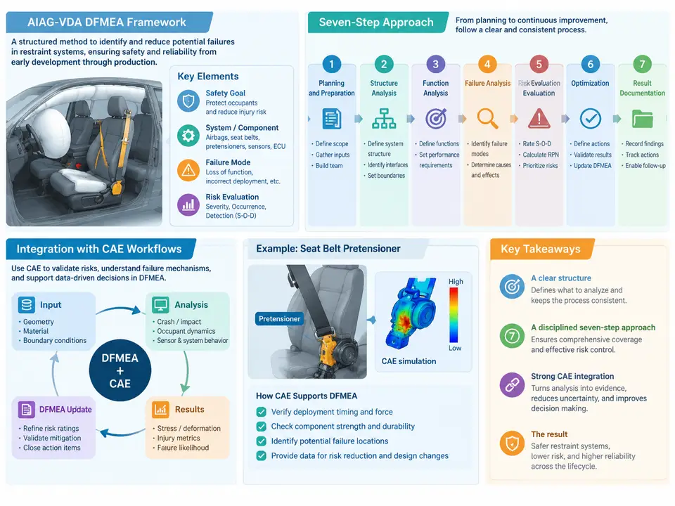
Restraint systems sit at the intersection of safety-critical function and highly non-linear physics. An airbag control unit must decide, within milliseconds, whether a crash event warrants deployment; a seat-belt retractor must lock at the right deceleration threshold; a side-curtain inflator must fill a cushion fast enough to protect an occupant's head without over-pressurizing the trim. Because these behaviors are governed by coupled structural, fluid, and control dynamics, the Design Failure Mode and Effects Analysis (DFMEA) for restraint systems cannot be a paper exercise completed after the design is frozen. The AIAG-VDA DFMEA framework, published in 2019 as a harmonized replacement for the earlier AIAG and VDA approaches, provides a structured, risk-driven method that maps naturally onto CAE workflows — provided the analyst understands how the seven steps connect to simulation evidence.
Why the AIAG-VDA Structure Matters for Restraint Design
The framework organizes analysis around three linked layers: Structure (what the system is made of), Function (what each element must do), and Failure (how each function can fail and what the consequence is). For a restraint system, this layering is essential because a single physical component — say, the clock spring in the steering-wheel module — participates in multiple functions: it must conduct the driver-airbag firing current, maintain steering-wheel angle signal continuity, and survive rotational cycling. Each function carries its own failure modes, and each failure mode may be detected or prevented by different validation evidence, including CAE results.
The framework replaces the legacy Risk Priority Number (RPN) with Action Priority (AP), a three-level ranking (High, Medium, Low) derived from Severity (S), Occurrence (O), and Detection (D). This change matters in restraint work because RPN arithmetic could let a high-severity, low-occurrence failure (e.g., inadvertent deployment at low speed) be numerically masked by a moderate-severity, high-occurrence cosmetic issue. AP forces the team to treat severity as a gating consideration, which aligns with the safety culture around Supplemental Restraint Systems (SRS).
The Seven-Step Approach in a Restraint Context
The seven steps are sequential but iterative: findings from later steps routinely send the team back to refine earlier structure or function definitions.
- Planning and Preparation (Step 1). Define scope, boundaries, customer requirements, and the analysis team. For a driver frontal airbag module, the boundary might include the inflator, cushion, module housing, retainer ring, and wiring harness interface, while explicitly excluding the steering-wheel structure and the ACU decision logic (handled in a separate DFMEA).
- Structure Analysis (Step 2). Decompose the system into system, subsystem, and component levels. A restraint system might be structured as: System = Occupant Restraint System; Subsystem = Frontal Airbag, Seat-Belt System, Side Airbag; Component = inflator, cushion, retractor, buckle, pretensioner.
- Function Analysis (Step 3). Assign functions and requirements to each structure element. Example: "Inflator shall deliver 100% of nominal gas output within 25 ms at 23 °C ± 5 °C, producing cushion internal pressure of 45–65 kPa at 40 ms."
- Failure Analysis (Step 4). Derive failure modes, effects, and causes. A failure mode for the inflator function might be "insufficient gas output," with effects at the vehicle level (inadequate occupant protection, increased injury criteria) and causes at the component level (propellant degradation, filter blockage, initiator energy deficit).
- Risk Analysis (Step 5). Assign S, O, and D ratings, then derive AP. Severity is rated against the effect on the end user or vehicle; occurrence against the cause's likelihood given current prevention controls; detection against the ability of current validation to catch the failure before production.
- Optimization (Step 6). Define and track actions to reduce risk — design changes, additional validation, or revised detection methods. Each action is assigned an owner and a due date, and the resulting S/O/D are re-evaluated.
- Results Documentation (Step 7). Consolidate the analysis into a report that captures the final risk profile, open actions, and the evidence base. This is where CAE reports, test data, and supplier PPAP evidence are cross-referenced.
Where CAE Fits: Evidence, Not Decoration
The most common failure in restraint DFMEA practice is treating CAE as a checkbox: a simulation is run, a report is filed, and the Detection rating is lowered without a defensible link between the simulation and the failure mode. The AIAG-VDA framework expects detection ratings to reflect demonstrated detection capability. For CAE to legitimately influence D, the simulation must be validated against physical test correlation, and its coverage must match the failure mode being analyzed.
Consider the failure mode "cushion tear at the seam during deployment." A CAE model using a calibrated fabric material model (e.g., an orthotropic membrane with strain-rate dependence) and a validated seam representation can detect this mode if the simulation explicitly models seam elements and the loading path that produces the tear. If the model uses a simplified shell without seam detail, the simulation cannot detect the mode, and D should not be reduced on its basis. This distinction — between a simulation that could reveal a failure and one that does — is the core of credible CAE integration.
Integrating CAE into the Seven Steps
The integration is not a single hand-off but a set of touchpoints across the workflow. The SVG below maps the seven steps to the CAE activities and evidence artifacts that feed each one.
A Worked Example: Inflator Gas Output
To make the integration concrete, consider the inflator function introduced earlier: "deliver 100% of nominal gas output within 25 ms at 23 °C." The DFMEA team identifies the failure mode "reduced gas output," with the vehicle-level effect "insufficient cushion pressure, elevated occupant injury criteria." The cause is "propellant burn-rate variation due to lot-to-lot moisture content."
In Step 5, the team assigns Severity 9 (potential for serious injury), Occurrence 4 (supplier process capability data shows occasional drift), and Detection 5 (current validation relies on end-of-line leak test, which does not measure burn rate). The AP is High. In Step 6, the team defines two actions: (1) add a propellant moisture specification with incoming inspection, and (2) develop a CAE model of the inflator–cushion system to predict pressure-time history as a function of burn rate. The CAE action is not a detection control by itself — it is a design-robustness tool that lets the team evaluate whether the cushion design tolerates the expected burn-rate range. After the model is correlated to a tank test at three burn-rate levels, the team can demonstrate that the cushion pressure remains within the 45–65 kPa window across the tolerance band, which supports reducing Occurrence from 4 to 3. Detection remains at 5 until a physical burn-rate screening method is added.
Practical Integration Rules
- One model version, one DFMEA revision. Record the CAE model version and solver in the DFMEA evidence column so that a later design change cannot silently invalidate the analysis.
- Match model fidelity to failure mode. A seam-tear mode needs seam-level detail; a system-level timing mode may be adequately covered by a lumped-parameter model. Over-modeling wastes resources; under-modeling produces false detection credit.
- Use CAE for Occurrence before Detection. Simulation is generally stronger at demonstrating design margin (Occurrence) than at proving detection capability (Detection), because detection also depends on the measurement method and sampling plan.
- Feed DOE results back into cause ranking. A sensitivity study that shows, for example, that inflator output is dominated by propellant moisture rather than filter porosity should reorder the cause list in Step 4 and focus optimization effort.
The AIAG-VDA framework is often described as a documentation standard, but in restraint engineering it functions as a reasoning discipline. Its seven steps force the team to separate what the system must do from how it can fail, and its Action Priority logic keeps severity visible. CAE earns its place in that discipline only when each simulation is traceable to a specific failure mode, correlated to physical evidence, and archived against a controlled model version. When those conditions hold, the DFMEA becomes a living risk register that the CAE team actively maintains — not a document completed once and filed away.