1. Capstone framing
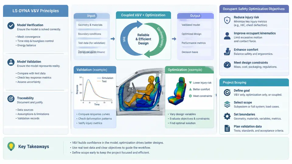
A capstone in LS-DYNA verification, validation, and occupant optimization is not a single simulation exercise. It is an engineering argument: a structured claim that a model, a workflow, and a design decision are credible enough to support a safety-relevant conclusion. The framing stage decides what that argument will be about, what evidence will support it, and how much of the coupled V&V-plus-optimization loop is actually tractable within the project window. Getting this framing wrong is the most common reason capstone projects stall — not solver instability, but an unfalsifiable objective, an uncalibrated model, or an optimization loop built on a validation basis that was never established.
Verification and validation are different claims
Verification asks whether the computational model solves the equations it is supposed to solve, correctly and consistently. Validation asks whether those equations, embodied in the model, represent the physical event of interest with sufficient accuracy for the intended use. In an occupant safety context, verification evidence includes mesh quality metrics, energy balance behavior, hourglass energy fraction, time-step stability, contact penetration checks, and convergence under refinement. Validation evidence includes correlation against physical test data — sled pulses, barrier impacts, component drop tests — using objective metrics such as peak acceleration, HIC, chest deflection, and pulse timing.
The distinction matters operationally because the two activities consume different resources and fail differently. A verified model with poor validation is a well-solved wrong problem. A validated model with weak verification may correlate by accident and will not extrapolate to design changes — which is exactly what an optimization loop demands. For a capstone, the practical rule is: verification is a gate before optimization, validation is the basis for trusting optimization outputs.
Occupant safety objectives must be measurable and bounded
Occupant optimization objectives are usually expressed as injury criteria and structural responses: HIC36, 3 ms chest acceleration clip, chest deflection, neck injury criteria (Nij), femur loads, and restraint-specific responses such as belt force and airbag pressure. A capstone objective must specify the criterion, the measurement location or output channel, the load case, and the acceptance threshold. "Reduce head injury" is not an objective. "Reduce HIC36 below 700 for the 50th-percentile Hybrid III driver in the 40 km/h frontal sled case, without increasing chest deflection above 50 mm" is an objective — it is measurable, bounded, and has a stated trade-off constraint.
Multi-objective framing is normal in occupant work because criteria conflict. Stiffer restraints reduce excursion but raise acceleration; earlier airbag deployment reduces head travel but can increase neck load for out-of-position occupants. The capstone should therefore declare which criteria are objectives (to be minimized), which are constraints (must not be violated), and which are observations (reported but not optimized). This declaration drives the entire downstream workflow: the design variables, the sampling plan, the surrogate model, and the acceptance logic.
Scoping the coupled V&V and optimization workflow
The coupling is the hard part. Optimization needs many runs; validation needs few but expensive ones. A capstone that tries to validate every design point will not finish; one that optimizes without a validated baseline produces numbers nobody should trust. The workable structure is a staged funnel: establish and verify a baseline model, validate it against available test data, then optimize within the validated envelope, and finally re-verify the selected optimum with a higher-fidelity or independent check.
The SVG below shows this funnel as a dependency structure rather than a linear checklist — note that the validation basis feeds the optimization envelope, and the final re-verification loops back to the same verification criteria used at the start.
What the capstone scope must pin down
Scoping is where most of the intellectual work happens. A defensible scope statement answers five questions concretely. First, which occupant and which load case — for example, a 50th-percentile Hybrid III in a 40 km/h frontal sled with a prescribed pulse, or a 5th-percentile female in a side impact. Second, which model fidelity — full vehicle, sled with body-in-white, or a component-level restraint model. Third, which design variables and their ranges, chosen so that the ranges are physically realizable and the DOE is affordable. Fourth, which criteria are objectives versus constraints, with numeric thresholds. Fifth, what evidence closes the project — the specific verification metrics, the validation correlation targets, and the re-verification check on the optimum.
A practical scoping heuristic for a capstone-sized effort: keep the design variable count in the range of four to eight, use a screening DOE (Plackett-Burman or a fractional factorial) to eliminate weak variables, then a space-filling design (Latin hypercube) of roughly 30–60 runs for the surrogate, and reserve two to four full-fidelity confirmation runs. These numbers are illustrative planning targets, not measured results — they should be adjusted to the available compute budget and the cost of a single LS-DYNA run.
A scoping worksheet you can actually fill in
The following table is a working template for the framing deliverable. Each row forces a concrete decision before any simulation is run. The example values are illustrative for a frontal sled capstone and should be replaced with project-specific choices.
| Scope element | Decision to record | Illustrative example |
|---|---|---|
| Occupant & load case | Dummy model, percentile, impact direction, pulse | Hybrid III 50th, frontal, 40 km/h sled pulse |
| Model fidelity | Full vehicle / sled / component | Sled with BIW + restraint system |
| Verification criteria | Metrics and pass thresholds | Hourglass < 5% internal energy; no penetration > 2 mm |
| Validation targets | Test data and correlation metric | HIC within ±10%, chest g peak within ±8% |
| Design variables | Names, ranges, units | Belt stiffness 40–80 N/mm; vent area 20–60 mm² |
| Objectives / constraints | Minimize / bound, with thresholds | Min HIC; constraint chest deflection ≤ 50 mm |
| DOE & surrogate | Design type, run count, model form | LHS 40 runs; kriging surrogate |
| Closing evidence | Re-verification and confirmation runs | 2 full-fidelity runs on selected optimum |
Why the framing determines success
The framing stage is not administrative overhead before the "real" work. It is the point where the capstone's credibility is either established or quietly undermined. A project that begins with a verified baseline, a validation basis with stated correlation targets, and an optimization envelope constrained to that basis will produce results that can be defended line by line. A project that begins with "optimize the restraint system" will produce a Pareto front of numbers whose relationship to physical safety is unknown. The remaining chapters build on this framing: the verification metrics introduced here become the gate criteria, the validation targets become the correlation standard, and the scoping worksheet becomes the project's controlling document. Treat the framing deliverable as a contract with yourself — every later decision should be traceable back to a row in that table.