1. DMAIC framework for crash simulation dis
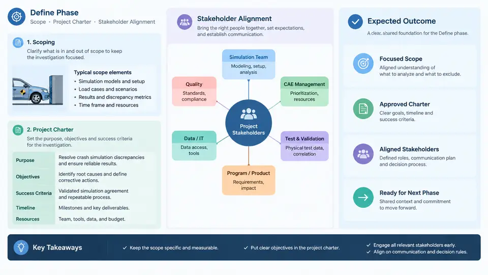
Crash simulation discrepancies rarely announce themselves with a clean error message. A frontal impact model may predict 62 mm of intrusion at the toe board while the physical sled test measures 78 mm; a side pole model may show the door latch releasing at 41 ms while the barrier test shows it holding until 55 ms. Before anyone opens a material card or re-meshes a rail, the investigation itself must be scoped. The Define phase of DMAIC exists precisely to convert a vague complaint ("the model doesn't match the test") into a bounded, measurable, and agreed-upon problem statement that the remaining four phases can actually solve.
In crashworthiness work, the temptation to skip Define is strong because the discrepancy feels self-evident. This is a mistake. A CAE correlation study without a defined scope drifts: engineers chase energy balance one week, contact definitions the next, and strain-rate sensitivity after that, while the test report's boundary conditions are never formally reconciled with the model's. The result is an investigation that consumes weeks and closes with "improved correlation" but no defensible root cause. Define prevents this by fixing four things before analysis begins: the response variable and its acceptance criterion, the model-versus-test comparison basis, the project boundary, and the decision authority.
Scoping the Discrepancy: From Symptom to Measurable Problem
Scoping begins with the response variable. A crash discrepancy must be expressed as a specific, instrumented quantity with a location, a direction, and a time window. "Cabin intrusion is too low" is not scoped. "Peak toe-board intrusion in the +X direction, measured at the left rocker reference node, within 0–120 ms, is 62 mm in the model versus 78 mm in test" is scoped. The same discipline applies to acceleration pulses (specify the channel, the filter class per SAE J211, and the CFC), to restraint outputs (belt force at the retractor, airbag pressure), and to structural failure events (spot-weld separation timing, hinge rotation).
Two scoping decisions carry disproportionate weight. First, the comparison basis: is the model being compared against a single test, a mean of repeated tests, or a test with known instrumentation uncertainty? Crash tests exhibit run-to-run variation of several percent even under nominally identical conditions, so a model that sits inside the test scatter may not have a real discrepancy at all. Define should record the number of valid repeats and the observed spread of the response variable. Second, the model fidelity boundary: which subsystems are in scope for correlation (e.g., front rail, bumper beam, engine mounts) and which are accepted as-is (e.g., the dummies, whose positioning error may itself explain part of the delta).
The SVG below shows how a Define-phase scope partitions a full vehicle model into the correlation envelope, the frozen boundary, and the excluded regions, with the response variable anchored to a specific measurement location.
The Project Charter: Making the Investigation Auditable
The charter is a one-page contract that survives personnel changes and management reviews. For a crash correlation project it should contain, at minimum, the following elements, each written concretely rather than generically.
| Charter element | Weak entry | Acceptable entry (example) |
|---|---|---|
| Problem statement | Model does not match test | Peak toe-board intrusion at left rocker node is 62 mm (model) vs 78 mm (test mean of 3 valid runs, σ = 2.1 mm) in 56 km/h ODB, 0–120 ms |
| Goal statement | Improve correlation | Bring model peak intrusion within ±5 mm of test mean and match pulse shape (peak timing within 5 ms) without exceeding 3 % change in total internal energy |
| Scope | Front end | Front structure per scope map; frozen boundary at firewall; dummies and inflator curves excluded |
| Metric / Y | Correlation quality | Δ intrusion (mm), Δ peak timing (ms), filtered acceleration CFC 60 correlation coefficient |
| Milestones | — | Measure: test data reconciled by week 2; Analyze: candidate causes ranked by week 5; Improve: validated model by week 8 |
| Team & authority | CAE group | CAE lead (owner), test engineer (data custodian), restraint SME, design release engineer; change approval by CAE manager |
Two charter fields deserve extra attention in crash work. The goal statement must include a guardrail against over-fitting: it is easy to tune a material card until one curve matches while silently degrading energy absorption elsewhere. Stating an energy-balance constraint (for example, total internal energy within 3 % of the baseline model, and no non-physical mass scaling introduced) keeps the Improve phase honest. The metric definition must pin down filtering and alignment, because a 5 ms time shift between model and test can flip a correlation coefficient from 0.92 to 0.61 without any physical difference in the structure.
Stakeholder Alignment: Who Owns Which Number
Discrepancy investigations fail politically more often than technically. The CAE engineer owns the model; the test engineer owns the data; the design release engineer owns the hardware definition; the restraint supplier owns the inflator curve. Each party can unilaterally invalidate the comparison — a re-run test with a different barrier face, a late design change to the rail gauge, an updated inflator file — and each has a different definition of "good enough." Define must surface these dependencies explicitly.
A practical alignment mechanism is a data custody agreement recorded in the charter: which test report revision is the reference, which model build (including solver version and include-file hashes) is the baseline, and who signs off on changes to either. For the example above, the charter might state: reference test report TR-2024-118 Rev C (three valid runs, runs 2 and 3 used for mean); baseline model build CAE-FR-0417 with LS-DYNA R13.1, include hash recorded; any change to the frozen boundary requires written approval from the CAE manager and notification to the test engineer within one business day.
Alignment also means agreeing in advance on what a successful outcome looks like and what happens if the root cause turns out to be a test-side issue. If the investigation concludes that the 16 mm delta originates from a load-cell calibration offset or a barrier alignment error rather than the model, the charter should already have established that this is a legitimate and reportable outcome — not a failure of the CAE team. Teams that pre-agree on this are far more willing to examine test data critically, which is often where the real cause lives.
Define Phase Exit Criteria
Define closes when the following are true and recorded: the response variable is quantified with location, direction, time window, and filter; the test reference (runs, mean, spread) is fixed; the scope map with in-scope, frozen, and excluded regions is signed off; the charter contains a measurable goal with an anti-over-fitting guardrail; the baseline model build is version-locked; and each stakeholder has an assigned responsibility for a specific data set or decision. Only then should the team move to Measure, where the test and simulation signals are time-aligned and the measurement system itself is characterized. Skipping any of these exit criteria does not save time — it merely defers the ambiguity into a later phase where it is more expensive to resolve.