1. Restraint system tuning landscape
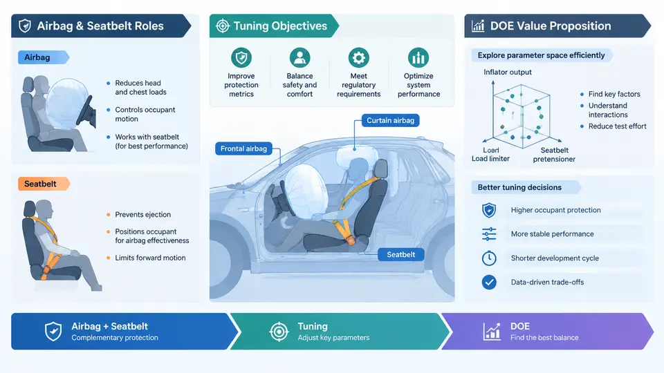
Occupant restraint tuning sits at the intersection of crash dynamics, hardware capability, and regulatory compliance. Before any statistical tool enters the picture, an engineer must understand what each subsystem contributes, what "good" looks like, and why the search for that optimum is genuinely difficult. This chapter establishes that shared mental model: the roles of airbags and seatbelts, the objectives that define a successful calibration, and the specific reasons why Design of Experiments (DOE) earns its place in the tuning workflow.
Two Subsystems, One Coupled Occupant Response
A modern restraint system is not a single device but a coordinated chain. The seatbelt is the primary, always-present restraint: it couples the occupant to the vehicle early in the crash pulse, manages the pelvis and torso, and — through load limiters and pretensioners — controls how much force reaches the chest. The airbag is a supplemental, event-triggered restraint: it deploys only when the crash severity and direction warrant it, and its job is to cushion the head and chest against interior structures during the forward excursion that the belt alone cannot fully arrest.
The word "supplemental" is deliberate. An airbag tuned to compensate for a poorly performing belt will produce an aggressive, high-energy deployment that harms small occupants and out-of-position cases. Conversely, a belt tuned without regard to the airbag's timing can allow the occupant to "pocket" into a deploying cushion or arrive at the airbag after it has already deflated. The two subsystems must be tuned as a coupled pair, and the occupant response — not the individual device — is the true output of interest.
Consider the physical sequence in a 56 km/h frontal barrier impact. Within roughly 10–20 ms the pretensioner fires and removes belt slack. The belt then begins loading the occupant, and the load limiter pays out webbing to cap shoulder-belt force, typically in the 3–5 kN range for a mid-size vehicle. The airbag, triggered by the crash sensor, begins inflating around 15–25 ms and reaches full inflation in the 30–50 ms window. The occupant's head arrives at the cushion somewhere around 50–70 ms. Every one of those timings is a tuning parameter, and every one interacts with the others.
What Tuning Actually Optimizes
Tuning objectives are multi-dimensional and frequently in conflict. The core injury metrics — head injury criterion (HIC), chest deflection, chest acceleration (3 ms clip), neck forces and moments, and femur loads — each respond differently to the same parameter change. A stiffer load limiter reduces chest deflection but raises head excursion and HIC risk. A higher airbag vent rate softens the cushion for a large occupant but may allow the head to bottom out against the module for a small one. There is no single knob that improves everything.
Beyond injury metrics, the calibration must satisfy regulatory and consumer-test requirements across a matrix of load cases: frontal rigid barrier at multiple speeds, offset deformable barrier, pole impacts, out-of-position (OOP) static deployment tests, and low-risk deployment for unbelted occupants. Each load case uses different dummies (Hybrid III 50th, 5th-percentile female, 95th-percentile male, and increasingly THOR), and each dummy has its own sensitivity to the same parameters. A calibration that passes the 50th-percentile frontal test may fail the 5th-percentile OOP test with the same airbag inflator.
The Parameter Space and Why It Is Hard to Search
The tunable parameters fall into a few families. On the belt side: pretensioner firing time and force profile, load-limiter force level (fixed or adaptive), and anchor geometry. On the airbag side: inflator output and burn profile, vent hole area and count, cushion volume and shape, tether configuration, and deployment timing relative to the crash pulse. Add the crash sensor's calibration (deployment threshold and algorithm) and the space quickly reaches dozens of dimensions.
Each evaluation is expensive. A single full-vehicle crash test costs tens of thousands of dollars and consumes a vehicle; a validated CAE sled or full-vehicle simulation takes hours to days per run. With a 20-parameter problem and even a coarse 3-level grid, a full factorial would require 320 ≈ 3.5 billion runs — utterly infeasible. This is the practical wall that motivates DOE: the parameter space is large, the evaluations are costly, and the response surface is non-linear and interacting.
The DOE Value Proposition
DOE addresses the search problem directly by choosing which runs to execute so that the information gained per run is maximized. Instead of varying one factor at a time — which cannot reveal interactions and wastes runs — a designed experiment spreads the runs across the parameter space in a structured pattern that allows the effects of each factor and their interactions to be estimated independently.
The workflow typically proceeds in stages. A screening stage uses a fractional factorial or Plackett–Burman design to identify, from perhaps 15–25 candidate parameters, the handful (often 4–8) that materially affect the injury metrics. A response-surface stage then fits a quadratic model — central composite or Box–Behnken designs are common — over the reduced parameter set, producing a surrogate that predicts HIC or chest deflection as a function of the key knobs. Finally, a robust optimization stage uses that surrogate to find a parameter set that minimizes worst-case injury across the load-case matrix while maintaining margin, and confirms it with a small number of validation runs.
The payoff is concrete. A screening design of 20 runs can replace hundreds of one-at-a-time trials and, critically, exposes interactions that one-at-a-time testing structurally cannot see — for example, that the benefit of a softer load limiter depends on the airbag vent area. The surrogate model also lets the engineer interrogate the design space cheaply: sensitivity plots, contour maps of HIC versus limiter force and vent area, and trade-off curves between chest deflection and head excursion become available without additional crash tests.
A Worked Framing Example
Suppose a frontal calibration has 18 candidate parameters and the team must reduce 50th-percentile HIC and chest deflection while keeping 5th-percentile OOP metrics within limits. A Plackett–Burman screening design with 20 runs (19 factors plus one center point) can rank the 18 parameters by main effect. Assume the screening identifies five dominant factors: load-limiter force, pretensioner fire time, vent area, inflator output, and cushion tether length. A central composite design over these five factors requires roughly 27–50 runs depending on the number of center and axial points. Fitting a second-order model to those runs yields a response surface; the engineer then locates the region where predicted HIC and chest deflection are both minimized subject to the OOP constraint, and validates that candidate with three to five confirmation runs. The total run count — on the order of 50–75 — is a small fraction of what an unstructured search would demand, and the resulting model documents why the chosen point is robust, not merely that it passed.
This is the landscape the rest of the course operates in: a coupled, multi-objective, expensive-to-evaluate tuning problem where structured experimentation is not a luxury but the only practical path to a defensible calibration.