1. Program initiation and scoping
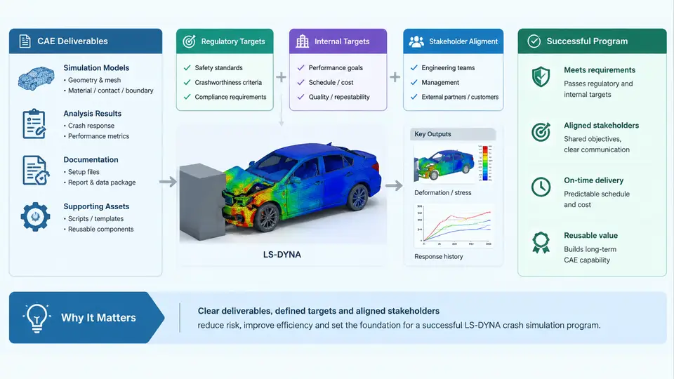
A crash simulation program rarely fails because the solver could not converge. It fails far earlier, at the moment when nobody agreed on what the model was supposed to prove. Program initiation and scoping is therefore not administrative overhead — it is the phase where the technical contract of the entire CAE program is written. For an LS-DYNA crash simulation program, scoping means converting a vehicle program milestone (for example, "FMVSS 208 certification at prototype build 2") into a set of explicit deliverables, load cases, acceptance criteria, model fidelity levels, and a schedule that the CAE team, the body structure group, the restraint systems group, and the program management office all accept as binding.
From Program Milestone to CAE Deliverable
The starting input is the vehicle program timing plan and the regulatory and internal safety targets. A typical scoping session begins with a matrix that maps each milestone to the CAE evidence required at that gate. The deliverable is never "a simulation"; it is a specific model, at a specific fidelity, answering a specific question, with a defined acceptance threshold.
Consider a frontal offset program. At the concept gate, the deliverable might be a coarse full-vehicle model with a simplified powertrain and rigid barriers, used only to compare two front rail load paths. At the design gate, the deliverable becomes a detailed model with validated material cards, a deformable barrier, and a calibrated occupant restraint model, used to demonstrate that the occupant injury criteria meet the target. The same physical event is simulated at three different fidelity levels, and each level has its own acceptance criterion. Writing this explicitly prevents the classic failure mode where a concept-level model is later judged against a certification-level threshold.
Regulatory and Internal Targets
Regulatory targets are fixed and non-negotiable: FMVSS 208, FMVSS 214, FMVSS 216a, ECE R94/R95, Euro NCAP, C-NCAP, or the applicable regional combination. Internal targets are stricter and are set by the OEM to create margin. A common practice is to define an internal target that is 10–15% more severe than the regulatory limit, so that production variation, material scatter, and build tolerances do not push the certified vehicle over the limit.
Each target must be expressed as a measurable quantity with a defined measurement location and a defined filtering method. "Chest deflection below 42 mm" is not sufficient; the scoping document must state the measurement point, the channel, the filter class (for example, CFC 600 for chest deflection per SAE J211), and the sign convention. In LS-DYNA this translates directly into *DATABASE_HISTORY_NODE and *DATABASE_ASCII_option cards, and into the coordinate system in which the deflection is reported. If the scoping document does not fix the sign convention, two engineers will report opposite signs for the same physical motion.
Stakeholder Alignment
The stakeholders of a crash simulation program are not only the CAE analysts. They include the body-in-white design owner, the restraint system integrator, the materials group (who own the material cards), the test group (who own the physical correlation data), the program timing owner, and the safety attribute owner who signs off on the targets. Each of these groups supplies an input that the CAE model cannot be built without.
Alignment is achieved through a scoping document that is reviewed and signed before any meshing begins. The document should contain, at minimum: the load case list with barrier type and impact speed, the model fidelity level per load case, the material card source and validation status, the occupant model version, the output request list, the acceptance criteria, the delivery date per milestone, and the named owner of each item. A useful discipline is to record, for every load case, which stakeholder requested it and which stakeholder will consume the result. Load cases with no consumer are candidates for deletion — they consume solver time and produce no decision.
Model Fidelity and Its Cost
Fidelity is the single most important scoping decision because it drives cost, schedule, and confidence. A useful way to frame it is to define three levels explicitly and assign each load case to one level.
| Fidelity level | Typical content | Typical element size | Typical use |
|---|---|---|---|
| L0 — Concept | Coarse shell mesh, rigid barriers, simplified powertrain, no occupant | 15–25 mm | Load path comparison, packaging studies |
| L1 — Design | Detailed shell mesh, deformable barrier, validated material cards, simplified occupant | 5–10 mm | Structure performance, restraint packaging |
| L2 — Certification | Full detail, calibrated occupant, validated barrier, correlation to test | 3–5 mm | Regulatory demonstration, sign-off |
The element sizes above are illustrative and must be confirmed against the program's correlation requirements; a 5 mm model that has never been correlated against a physical test carries less confidence than a 10 mm model that has. Fidelity is not the same as mesh density — it is the combination of mesh density, material representation, contact definition, and validation status.
Scoping Workflow
The diagram below shows how the scoping inputs converge into a signed scoping document, and how that document then drives the model build. The key point is that the acceptance criteria and the output requests are defined before the model is built, not extracted from the results afterwards.
A Practical Scoping Template
The following excerpt shows how a single load case is recorded in the scoping document. It is deliberately compact so that it can be reviewed in a one-hour alignment meeting.
Load case ID:        FRO-64-ODB
Description:         Frontal 40% offset deformable barrier, 64 km/h
Regulation:          FMVSS 208 / ECE R94
Internal target:     occupant chest deflection <= 36 mm (10% margin)
Fidelity level:      L1 at design gate, L2 at certification gate
Barrier:             ECE R94 deformable barrier, 1000 kg trolley
Initial velocity:    17.78 m/s along -X (vehicle forward = +X)
Model source:        BIW_DSGN_v3.k, restraint model RS_v2.k
Material cards:      MAT_024 / MAT_123, validated against coupon tests
Output requests:     *DATABASE_BINARY_D3PLOT (2 ms interval)
                     *DATABASE_HISTORY_NODE (chest, pelvis, head)
                     *DATABASE_ASCII_option (resultant forces)
Acceptance check:    chest deflection channel CFC 600, sign +ve = rearward
Owner:               CAE lead (model), restraints (occupant), test (correlation)
Delivery:            design gate, week 18
Two details in this template deserve emphasis. First, the initial velocity direction is stated explicitly with the vehicle coordinate convention, because LS-DYNA applies initial velocity through *INITIAL_VELOCITY and a sign error produces a simulation of a rear impact. Second, the acceptance check names the filter class and the sign convention, which removes the most common source of post-processing disputes.
Common Scoping Failures and How to Detect Them
The most frequent failure is the moving target: the acceptance criterion is quietly relaxed after the first result shows a violation. The defence is to freeze the criteria in the signed document and require a formal change record for any modification. The second failure is fidelity mismatch, where a concept-level model is used to answer a certification-level question; this is detectable by checking that the model's correlation status matches the fidelity level claimed in the scoping document. The third failure is orphan load cases — cases that no stakeholder consumes. A simple audit at the end of scoping, listing each load case with its requesting and consuming stakeholder, usually removes 10–20% of the planned runs and returns that solver time to the cases that actually drive decisions.
When the scoping document is signed, the program has a stable technical baseline. The model build, the load case setup, and the correlation work that follow all inherit their requirements from this document, and every later dispute about "whether the simulation passed" can be resolved by returning to the criteria and conventions recorded here.