1. Occupant restraint CAE campaign scope
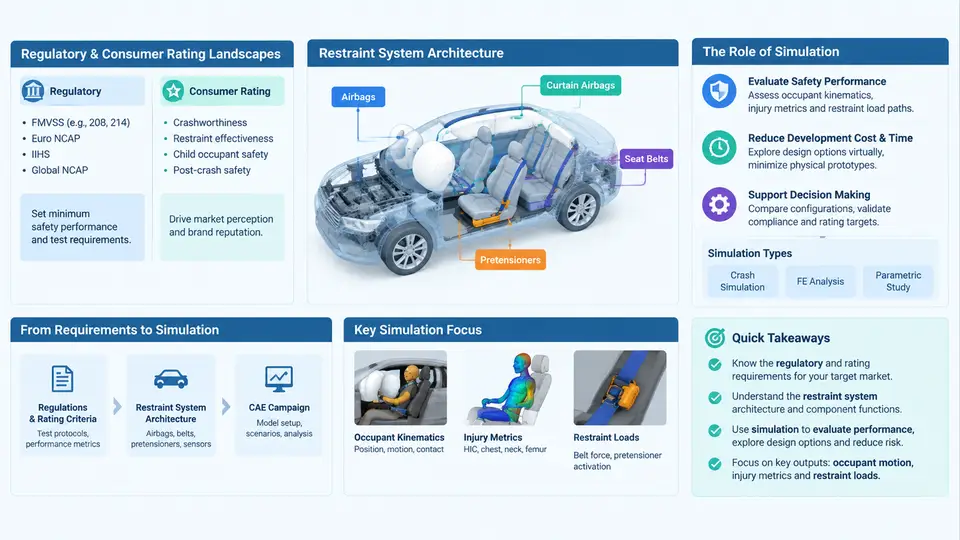
An occupant restraint CAE campaign is not a single simulation run; it is a managed program of load cases, models, and deliverables that must satisfy both legal minimums and consumer-rating targets while fitting inside a vehicle program's timing and budget. Before any solver deck is written, the CAE engineer must answer three framing questions: Which regulations and rating programs apply? What restraint hardware is actually in the vehicle? and Where in the development timeline does simulation create the most value? Getting these wrong produces expensive rework — a sled model built for FMVSS 208 that ignores Euro NCAP's mobile progressive deformable barrier (MPDB) requirements, or a side-airbag model that never accounts for the far-side occupant.
Regulatory versus consumer-rating landscapes
Restraint CAE sits between two distinct evaluation systems. Regulations are pass/fail legal requirements: FMVSS 208 (frontal, US), FMVSS 214 (side impact and pole), FMVSS 226 (ejection mitigation), ECE R94/R95 (European frontal and side), and GB 11551/20071 (China). They define fixed barriers, fixed speeds, fixed dummy types, and hard injury thresholds. Consumer rating programs — US NCAP, Euro NCAP, C-NCAP, Latin NCAP, ANCAP, and JNCAP — are scored, updated on roughly a three-to-five-year cadence, and typically demand more severe or more varied loading than the regulation they overlap with.
The practical consequence is that a single vehicle must be evaluated against a matrix, not a list. The table below shows a representative frontal subset for a mid-size passenger car; note how the same physical structure is loaded differently by each program.
| Program | Test type | Speed | Barrier / impactor | Key dummy | Primary metric |
|---|---|---|---|---|---|
| FMVSS 208 | Full frontal rigid | 56 km/h | Rigid wall | Hybrid III 50th | HIC, chest deflection, femur load |
| FMVSS 208 | Offset deformable | 40 km/h | ODB (fixed) | Hybrid III 5th (small female) | HIC15, Nij, chest |
| Euro NCAP | Offset deformable | 64 km/h | ODB | Hybrid III 50th | HIC15, chest, knee |
| Euro NCAP | MPDB | 50 km/h | MPDB + oncoming trolley | THOR 50th | HIC, chest, compatibility (ODB) |
| C-NCAP | Full frontal rigid | 50 km/h | Rigid wall | Hybrid III 50th | HIC, chest, femur |
Two engineering implications follow immediately. First, dummy choice drives model fidelity: a THOR 50th percentile model has far more instrumentation channels and a different biofidelity envelope than a Hybrid III, so the restraint model must be validated against the correct dummy. Second, barrier choice drives structural loading: MPDB introduces a moving deformable barrier and a compatibility assessment, which changes the energy management strategy compared with a fixed ODB. A CAE campaign that does not explicitly map load cases to programs will silently miss coverage.
Restraint system architecture
The restraint system is a coordinated set of energy-absorbing and load-limiting devices. For CAE purposes it is useful to decompose it into four interacting subsystems:
- Structural interface — body-in-white crush zones, rocker and B-pillar stiffness, floor and seat mounting points. These define the deceleration pulse and the boundary conditions the restraints work against.
- Occupant packaging — seat geometry, H-point, seat belt anchorage locations (per FMVSS 210 / ECE R14), steering column and knee bolster positions. Packaging sets the available ride-down distance.
- Restraint devices — seat belts with pretensioners and load limiters, dual-stage airbags, side and curtain airbags, knee airbags, and increasingly far-side airbags. Each has its own deployment timing and force-deflection characteristic.
- Sensing and control — crash sensors, occupant classification, and the airbag control unit (ACU) that decides deployment timing and stage. In CAE this is represented as a prescribed trigger time or a simplified sensor model.
The critical insight for campaign management is that these subsystems are coupled. Changing the load limiter force changes chest deflection but also changes occupant kinematics and therefore airbag interaction. Changing the pretensioner timing changes belt slack and therefore the effective ride-down. A CAE campaign must therefore be organized around parameter sweeps and design-of-experiments, not isolated single runs.
The role of simulation in vehicle development
Simulation does not replace physical testing; it de-risks and prioritizes it. In a typical program, the restraint CAE campaign runs through four phases that mirror the vehicle development timeline:
- Concept phase — simplified sled models and occupant packaging studies. The goal is to establish feasible ride-down distance, belt geometry, and airbag volume. These models use a prescribed deceleration pulse rather than a full BIW model, so they run in minutes and allow rapid trade studies.
- Design phase — full-vehicle or detailed sled models with parameterized restraint components. This is where DOE and optimization happen: load limiter force, pretensioner timing, airbag vent size, and tether length are swept against injury criteria. Hundreds of runs are common.
- Validation phase — correlation against physical sled and full-vehicle tests. The model is tuned so that predicted occupant kinematics and injury values match measured data within an agreed tolerance (typically ±10–15% on HIC and chest deflection).
- Homologation support — the validated model is used to generate evidence for regulatory submissions and to support rating-program documentation, and to assess late design changes without a full physical test.
The value of simulation is highest in phases 1 and 2, where physical prototypes do not yet exist. A well-scoped campaign can eliminate dozens of physical tests by identifying infeasible designs early. The cost of a poorly scoped campaign is equally clear: late discovery that a restraint configuration fails a rating threshold forces expensive hardware changes and schedule slips.
What a campaign scope document must contain
A practical campaign scope is a controlled document that a CAE manager can hand to a simulation engineer and a test engineer without ambiguity. At minimum it should capture:
- Target markets and program versions — which regulations and rating protocols apply, with the specific revision year.
- Load-case list — each case with impact type, speed, barrier/impactor, dummy type and percentile, and the injury criteria to be reported.
- Restraint configuration baseline — belt type, pretensioner, load limiter, airbag sizes and venting, ACU trigger times.
- Design variables and ranges — the parameters to be swept, with lower and upper bounds and any constraints.
- Model fidelity level — sled vs. full-vehicle, dummy model version, mesh criteria, and correlation targets.
- Deliverables and timing — reports, injury tables, and the program milestones they support.
With this scope defined, the campaign becomes executable: each load case maps to a model, each model maps to a set of runs, and each run produces a measurable output that can be compared against a threshold. The remaining chapters of this course build on this foundation, moving from scope definition into model construction, load-case execution, correlation, and campaign reporting.