1. Course overview
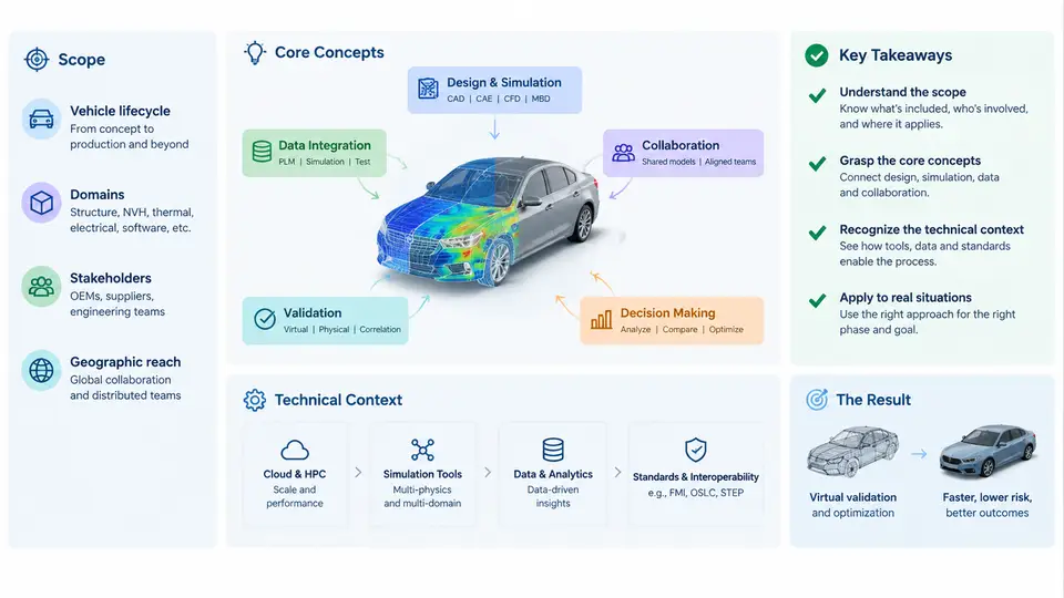
Automotive virtual engineering delivery is the discipline of producing, validating, and handing over engineering evidence through simulation and model-based methods rather than through physical prototypes alone. In a modern vehicle program, a large share of the decisions that were once made on test tracks and in crash halls are now made in CAE solvers, system simulation tools, HIL benches, and digital mock-up environments. The deliverable is no longer just a part or a drawing; it is a traceable chain of models, assumptions, load cases, results, and acceptance decisions that a receiving team can audit and reuse.
This course examines that delivery chain through case studies. Each chapter takes a realistic engineering situation — a durability sign-off, a thermal management trade study, a brake NVH investigation, an ADAS sensor coverage assessment — and works through how the virtual work was scoped, executed, checked, and accepted. The goal is not to teach one solver's menu structure, but to build the judgement that separates a simulation that merely runs from a simulation that can be defended in a design review.
What "Delivery" Means in a Virtual Program
The word delivery is deliberate. In automotive practice, virtual engineering is judged by the same criteria as physical testing: a defined requirement, a defined method, a defined acceptance threshold, and a documented result. A CAE analyst who produces a contour plot has done analysis. An engineer who produces a signed-off stiffness value with a mesh convergence study, a correlated material card, and a documented load case has made a delivery.
Three properties distinguish a delivery from an activity:
- Traceability — every result can be traced back to a requirement, a model version, a boundary condition set, and a solver version.
- Reproducibility — a second engineer, given the same inputs and deck, obtains the same result within a stated tolerance.
- Decision value — the result changes or confirms a design decision, and the acceptance criterion is stated before the result is known.
In a typical OEM or Tier-1 workflow, these properties are enforced through a simulation data management (SDM) system, a CAE methodology guide, and a formal sign-off matrix. The case studies in this course repeatedly return to those three artefacts because most real failures in virtual delivery are failures of traceability or of pre-defined acceptance, not failures of solver capability.
The Technical Context: Where Virtual Work Sits in the V-Model
Automotive development follows a V-model: requirements decompose on the left branch, subsystems are realised in the middle, and verification and validation climb the right branch. Virtual engineering is not confined to one point on that V. It supports requirement decomposition (system simulation, target cascading), design synthesis (CAD and DMU), component verification (CAE), and system validation (HIL, SIL, vehicle-level simulation).
The figure below maps the principal virtual delivery streams onto the V-model and shows the data that flows between them. The key point is that these streams are coupled: a body-in-white stiffness result feeds the durability load case, which feeds the fatigue life prediction, which feeds the weight-reduction decision. Breaking that chain is the most common cause of a delivery that cannot be defended.
Core Concepts and Vocabulary
Before the case studies begin, it is worth fixing the vocabulary that will recur throughout the course. These terms are used consistently in OEM methodology documents and in supplier statements of work.
| Term | Working definition | Typical artefact |
|---|---|---|
| Load case | A defined combination of boundary conditions, loads, and environment that the model must withstand or perform under. | Load case matrix, boundary condition deck |
| Correlation | Quantitative agreement between a simulation result and a physical measurement under matched conditions. | Correlation report, MAC / frequency error table |
| Model fidelity | The level of physical detail represented, chosen to match the decision the model must support. | Mesh convergence study, element quality report |
| Sign-off matrix | A table mapping each requirement to the method, threshold, and responsible engineer that will demonstrate compliance. | DVP&R (Design Verification Plan and Report) |
| Margin | The quantified difference between the predicted result and the acceptance threshold, including uncertainty allowance. | Margin table, safety factor summary |
Two of these deserve emphasis. Model fidelity is a decision, not a default. A full-vehicle crash model with 15 million elements is appropriate for occupant injury prediction and wasteful for a bracket stiffness check. The case studies will show engineers choosing fidelity deliberately and documenting why. Margin is where virtual delivery most often goes wrong: a result that passes by 2% with an unquantified material scatter is not a pass, it is an unresolved risk.
How the Case Studies Are Structured
Each chapter follows the same underlying logic without forcing a rigid template. A case opens with the engineering question and the acceptance criterion. It then establishes the model — geometry source, mesh strategy, material data, boundary conditions — with enough specificity that the reader can see the actual inputs. The execution section shows the solver setup, the key parameters, and the convergence or stability checks that were applied. The results section presents the observable output and the interpretation, including what a marginal or failing result looks like. Finally, the delivery section shows how the result was packaged: what was handed over, to whom, and with what caveats.
Where a case produces a reusable artefact — a load case definition, a correlation checklist, a margin table — that artefact is given in full so it can be adapted. Where a case turns on a judgement call, the reasoning is made explicit rather than presented as a rule.
What You Should Be Able to Do After This Course
By the end of the thirty chapters, you should be able to take a virtual engineering request, determine what fidelity and method are appropriate, define the acceptance criterion before running the model, execute the analysis with documented inputs, interpret the result including its uncertainty, and package the delivery so that a design team or a customer can act on it. You should also be able to recognise the common failure modes — unconverged solutions presented as results, boundary conditions copied from an unrelated load case, correlation claimed without matched test conditions — and to challenge them constructively in a review.
The technical context is broad: structural CAE, CFD, multibody dynamics, system simulation, HIL and SIL, and the data management that ties them together. The course does not attempt to make you an expert in every solver. It aims to make you fluent in the delivery process that gives any of those solvers its engineering value.