1. Crash simulation in automotive engineeri
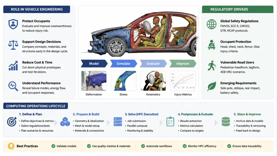
Crash simulation is the numerical reproduction of a vehicle structure's response to an impact event. In modern vehicle development it is not a single analysis but a family of explicit-dynamics finite element (FE) simulations — frontal offset, full frontal rigid barrier, side MDB (moving deformable barrier), pole, rear, and pedestrian impact — each with its own barrier, impact velocity, and occupant or structural acceptance criteria. The simulation engineer's job is to make those models run reliably, at scale, and with results that can be trusted for design decisions. That is the domain of crash simulation computing operations: the discipline of managing the models, solvers, hardware, data, and workflows that turn a crash model into a defensible result.
Why Crash Simulation Exists in the Development Loop
A full-vehicle crash model typically contains 5–15 million elements, hundreds of material definitions, contact interfaces, spot welds, and a detailed occupant restraint system. A single 150 ms frontal impact solved with LS-DYNA on a modern HPC cluster may consume 2,000–20,000 core-hours. Physical prototypes cost far more and arrive late in the program. Simulation therefore serves three roles:
- Design guidance — comparing structural concepts (e.g., hot-stamped B-pillar vs. tailored blank) before any hardware exists.
- Certification evidence — supporting homologation and internal safety targets with correlated CAE results.
- Root-cause analysis — explaining a physical test failure (e.g., a door latch release) by replaying the event numerically.
The consequence for operations is that crash models are large, long-running, and run in batches. A single vehicle program may execute thousands of crash jobs across a development cycle, and each job must be traceable to a model revision, a solver version, and a result set.
Regulatory and Rating Drivers
Crash simulation requirements are shaped by regulation and consumer rating, and these directly determine what must be computed and how results are judged.
| Driver | Typical Load Case | Key Acceptance Metric |
|---|---|---|
| FMVSS 208 | Full frontal rigid barrier, 56 km/h; offset deformable barrier | Occupant injury criteria (HIC, chest deflection, femur load) |
| FMVSS 214 / side impact | MDB side impact, 54 km/h | Rib deflection, pelvic force, door intrusion |
| Euro NCAP | Frontal offset (MPDB), side MDB, pole | Star rating, structural intrusion limits |
| Pedestrian protection (GTR 9) | Legform, upper legform, headform impacts | Bending angle, shear, HIC |
These load cases are not optional. A model that cannot reproduce them within tolerance cannot support a certification claim. This is why crash simulation operations must enforce model quality gates — units, mass, initial velocity, contact definitions, and boundary conditions — before a job is allowed to consume cluster time.
The Computing Operations Lifecycle
Crash simulation computing operations is best understood as a lifecycle with five stages. Each stage has inputs, controls, and exit criteria.
- Model preparation and intake. The CAE model (typically a
.keyor.kLS-DYNA deck, or a.radRadioss deck) is checked for unit consistency, mass, and completeness. A common failure is a mixed-unit deck: lengths in mm, mass in tonnes, time in seconds, but a material density entered in kg/mm³. The resulting model runs but produces nonsense. Intake validation catches this before submission. - Job configuration and submission. The solver input is assembled with the correct number of MPI ranks, memory allocation, and termination time. For LS-DYNA, a typical submission looks like:
# Example LS-DYNA SMP/MPP submission (illustrative)
lsdyna i=vehicle_frontal.k \
       ncpu=64 \
       memory=2000m \
       t=0.150 \
       d3plot=0.002 \
       endtim=0.150 \
       jobid=FRONTAL_R03
Here ncpu=64 requests 64 MPI ranks, memory=2000m allocates 2 GB per rank, t=0.150 sets the termination time to 150 ms, and d3plot=0.002 writes a state every 2 ms. These are illustrative values; actual settings depend on model size and cluster policy.
- Execution and monitoring. The job runs on the cluster. Operations staff monitor wall-clock time, memory usage, and the solver's
d3hspormessagfile for warnings. A negative volume, an excessive time-step reduction, or a contact penetration warning are early indicators of a model problem, not a hardware problem. - Result extraction and validation. After termination, the
d3plotdatabase is post-processed to extract intrusion, acceleration, and energy curves. The energy balance is the first sanity check: total energy should be conserved, and hourglass energy should remain below roughly 5% of internal energy. A rising hourglass energy indicates insufficient element formulation control. - Archival and traceability. The model revision, solver version, input deck, and result set are archived together. Without this, a result cannot be reproduced or defended in a design review.
Visualizing the Lifecycle and Its Feedback Loops
The diagram below shows the five stages and the two critical feedback paths: model corrections returning to intake, and result validation feeding back into job configuration when a run is inconclusive.
What Operations Must Guarantee
Three guarantees separate a working crash simulation operation from an ad hoc one. First, reproducibility: the same model revision and solver version must produce the same result. This requires version pinning and archived input decks. Second, throughput: a design iteration may require 20–50 crash runs in a week, so job scheduling, license management, and queue policy matter as much as solver settings. Third, traceability: every result must be linked to the model revision and load case that produced it, because a crash result without provenance cannot support a design or certification decision.
d3plot — but every acceleration and intrusion value will be wrong. Mass and unit checks are the cheapest and highest-value gate in the entire lifecycle.
With this lifecycle in view, the remaining chapters of this course move from model preparation and solver configuration through cluster execution, result validation, and the operational practices that keep a crash simulation pipeline reliable at production scale.