1. Automotive CAE team leadership
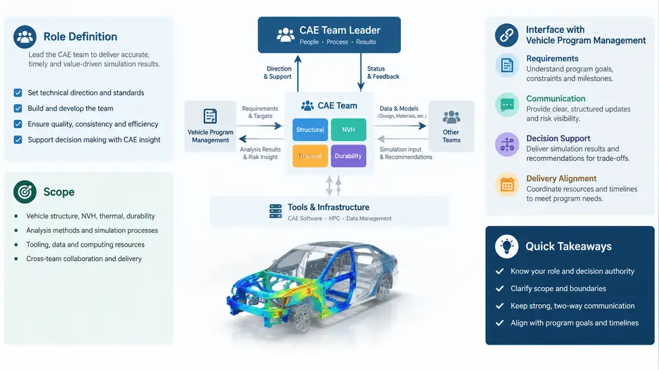
In an automotive OEM or Tier-1 engineering organization, the CAE team leader occupies a position that is simultaneously technical and organizational. The role is not simply "the most experienced simulation engineer in the room." It is a boundary-spanning function that translates vehicle program objectives into a simulation strategy, allocates scarce analytical resources, and defends CAE-derived conclusions in program forums where cost, timing, and mass targets compete directly with durability, NVH, crashworthiness, and thermal requirements. Understanding this role precisely — what it owns, what it influences, and what it merely supports — is the foundation for every subsequent coordination activity in this course.
What the CAE Team Leader Actually Owns
The CAE team leader's ownership can be grouped into four domains, each with a distinct deliverable and a distinct failure mode.
- Simulation strategy and model fidelity. Deciding which load cases, which solver fidelity (e.g., full vehicle explicit crash vs. simplified linear implicit), and which mesh resolution are appropriate for each program milestone. The deliverable is a CAE plan that maps analysis tasks to gate reviews. The failure mode is over-modeling early concepts and under-modeling at the final design verification.
- Resource and capacity management. Balancing solver licenses, HPC queue hours, and engineer workload across multiple concurrent programs. The deliverable is a capacity forecast. The failure mode is a bottleneck discovered two weeks before a design freeze.
- Technical quality and correlation. Ensuring that CAE predictions are validated against physical test data and that correlation metrics (e.g., peak acceleration within ±15%, intrusion within ±10 mm) are tracked and reported. The deliverable is a correlation status dashboard. The failure mode is a model that predicts well in one load case but is blindly trusted in another.
- Method development and standardization. Maintaining the team's simulation methodologies, automation scripts, and best-practice guidelines. The deliverable is a controlled method library. The failure mode is each engineer using a personal variant of the same load case, making results non-comparable.
Critically, the CAE team leader does not own the vehicle architecture, the bill of materials, or the program timing. Those belong to the vehicle program management team and the respective design functions. The CAE leader's authority is derived from the credibility of the analysis and the clarity of the recommendations, not from direct design ownership.
The Interface with Vehicle Program Management
Vehicle program management (VPM) is the function that owns the overall vehicle targets — mass, cost, timing, and attribute performance — and arbitrates trade-offs when they conflict. The CAE team leader interfaces with VPM through several recurring mechanisms:
| Interface Mechanism | CAE Leader's Input | VPM's Decision | Typical Frequency |
|---|---|---|---|
| Attribute target setting | Feasibility assessment: can the current architecture meet the stiffness, crash, and NVH targets? | Final attribute targets and priority ranking | Program kickoff and major gate reviews |
| Design gate reviews | CAE status: pass/fail/marginal per load case, with risk quantification | Gate pass, conditional pass, or redesign directive | Each program milestone (e.g., DR0–DR4) |
| Change impact assessment | Simulation turnaround time and predicted performance delta for proposed design changes | Approve, reject, or defer the change | Continuous during design phase |
| Resource escalation | Evidence of capacity shortfall or skill gap affecting program timing | Additional headcount, HPC allocation, or scope reduction | As needed, typically quarterly planning |
The most common friction point is timing. VPM operates on a cadence of design releases and gate reviews. CAE operates on a cadence of model build, solve, and post-process. When a design change is proposed late in a gate cycle, the CAE leader must decide whether to run a full-fidelity analysis (accurate but slow) or a simplified screening analysis (fast but approximate). This decision must be communicated explicitly to VPM, including the confidence level of the result. A CAE leader who silently delivers a low-confidence result as if it were definitive will eventually lose credibility; one who always demands more time will be bypassed.
Making the Interface Work: Practical Coordination Patterns
Effective CAE leaders use several concrete patterns to keep the VPM interface productive rather than adversarial.
1. The CAE status one-pager. Before every gate review, the CAE leader delivers a single-page summary that lists each attribute (e.g., frontal crash, side impact, body torsional stiffness, powertrain bending, HVAC cool-down), the current prediction, the target, the margin, and a confidence rating (High / Medium / Low). The confidence rating is based on correlation history: a load case with a validated model and recent test correlation earns High; a new load case with no test data earns Low. VPM can then make informed risk decisions rather than treating all CAE results as equally certain.
2. The change impact triage. When design engineering proposes a change — for example, reducing a B-pillar gauge from 1.8 mm to 1.5 mm for mass savings — the CAE leader does not simply run a full simulation. Instead, the team applies a triage logic: if the change affects a load path already covered by a validated simplified model (e.g., a beam-section stiffness calculation), the screening can be completed in hours. If it affects crash energy management, a full explicit run is required. The CAE leader communicates the triage decision and the expected turnaround to VPM, who can then decide whether to wait or to proceed with a conditional approval.
3. The correlation review cadence. After each physical test milestone, the CAE leader organizes a correlation review with the test team and design engineering. The goal is not to prove the model is perfect but to quantify the gap and decide whether the model needs updating before the next design iteration. A typical outcome might be: "The frontal crash model over-predicts peak deceleration by 12% at the tunnel; we will adjust the material card for the crash box and re-run the baseline before evaluating the next design change." This keeps the model honest and prevents the accumulation of unvalidated assumptions.
Scope Boundaries and Common Misalignments
Two misalignments recur frequently. First, VPM may expect CAE to optimize the design, when in fact CAE's role is to evaluate proposed designs and recommend directions. Optimization requires design variables and an objective function that only the design and program teams can define. Second, design engineering may treat CAE as a validation step at the end of a design phase, rather than as an upfront feasibility filter. The CAE leader must actively push analysis earlier into the concept phase, where the cost of change is low and the influence of simulation is highest.
A useful boundary statement for the CAE leader's role is: "We provide the physics-based evidence and the risk assessment; the program provides the decision and the resources." This framing respects the authority of VPM while asserting the technical independence of CAE. It also clarifies that when CAE says "this design will not meet the side impact target without a 15 kg mass increase," the program is free to accept the mass, change the target, or change the design — but it cannot claim it was not informed.
Key Takeaways
- The CAE team leader owns simulation strategy, capacity, correlation quality, and methods — not the vehicle design or program timing.
- The VPM interface is a two-way exchange: CAE provides feasibility, status, and risk; VPM provides targets, timing, and gate decisions.
- Confidence ratings, change triage logic, and correlation reviews are the practical mechanisms that make the interface work.
- Clear scope boundaries prevent the two most common misalignments: expecting CAE to optimize, and treating CAE as a late-stage validation only.