1. CAE data landscape in automotive enginee
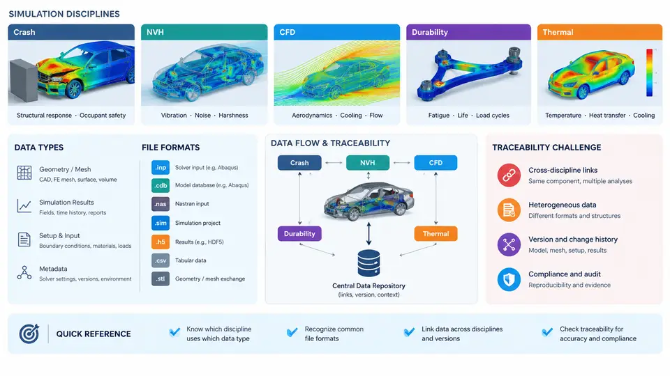
Modern vehicle development is no longer a single-discipline engineering exercise. A typical passenger car program runs dozens of concurrent simulation streams, each producing its own model files, solver decks, result databases, and post-processing artifacts. Before any data management or traceability system can be designed, engineers must first understand what kinds of CAE data actually exist, how they differ across disciplines, and why those differences make traceability genuinely hard.
Simulation Disciplines and Their Data Signatures
Five simulation domains dominate automotive CAE practice, and each has a distinct data profile in terms of model size, solver format, run frequency, and result volume.
Crash / Occupant Safety. Explicit dynamics codes such as LS-DYNA, PAM-CRASH, and Radioss dominate. A full-vehicle frontal impact model may contain 8–15 million elements, with solver decks in the hundreds of gigabytes. Result files (d3plot, anim, binout) are written at hundreds of time steps, producing terabytes per run. Crash CAE is characterized by low run frequency (tens of runs per program phase) but extremely high data volume per run.
NVH (Noise, Vibration, Harshness). Implicit solvers such as Nastran, OptiStruct, and Abaqus are standard. Models are typically 1–5 million DOF, and the critical outputs are frequency response functions, mode shapes, and transfer functions. NVH runs are frequent (hundreds per program) but each run produces comparatively compact result sets — often a few hundred megabytes of punch files and OP2 results.
CFD (Computational Fluid Dynamics). Tools like STAR-CCM+, Fluent, and PowerFLOW handle underhood thermal, aerodynamics, and HVAC ducting. Meshes are large (50–200 million cells for external aero), and transient runs generate time-series field data that can reach several terabytes. CFD is characterized by long wall-clock times and heavy post-processing demands.
Durability / Fatigue. FE-based fatigue tools (nCode, FE-SAFE, Femfat) consume stress/strain results from implicit or explicit solvers and combine them with load spectra. The data chain is multi-stage: load data → FE stress results → fatigue damage. Traceability here requires linking across at least three tool boundaries.
Thermal Analysis. Both steady-state and transient thermal runs (often coupled with CFD or structural codes) produce temperature field maps that feed into durability and NVH analyses. Thermal models are moderate in size but frequently coupled, creating cross-discipline dependencies.
Data Types and File Formats
CAE data falls into four broad categories, each with its own format ecosystem:
- Model / input data: CAD geometry (STEP, IGES, JT), meshes (Nastran BDF, LS-DYNA keyword, CDB), material cards, boundary conditions, and solver control decks.
- Solver output / results: Binary result databases (d3plot, OP2, UNV, EnSight case), punch files, and log files.
- Post-processing artifacts: Session files, report templates, screenshots, animations, and extracted XY plots.
- Metadata: Run logs, solver version, hardware info, input deck checksums, and analyst annotations.
The format fragmentation is severe. A single crash CAE run may involve a Nastran BDF for the body-in-white, an LS-DYNA keyword deck for the full vehicle, a d3plot for results, and an Excel spreadsheet for occupant injury criteria. None of these formats natively carry traceability metadata.
The Traceability Challenge
Traceability in CAE means answering a deceptively simple question: for any given simulation result, what exact model, material data, boundary conditions, solver version, and analyst decisions produced it? In practice, this question is difficult for several reasons.
Cross-discipline dependencies. A durability result depends on a thermal result, which depends on a CFD result, which depends on a CAD geometry that may have been revised three times since the CFD run. Without explicit linkage, the chain breaks silently.
Version proliferation. A single crash model may exist in 40+ variants across a program — different trim levels, different restraint configurations, different mesh updates. Naming conventions alone cannot reliably distinguish them.
Tool-boundary metadata loss. When a Nastran OP2 is imported into nCode, the original solver version, run ID, and input deck hash are typically lost. The fatigue result inherits none of the upstream provenance.
Human factors. Analysts often work in local directories, rename files informally, and share results via email or network drives. The "official" result may be indistinguishable from a draft.
Why This Matters for System Design
The practical consequence of this landscape is that a CAE data management system cannot be a simple file repository. It must capture relationships — between a mesh and the CAD revision it was derived from, between a solver run and the input deck that drove it, between a fatigue result and the thermal load case that fed it. It must also handle the reality that different disciplines produce data at different rates, in different formats, and with different retention requirements.
A useful mental model is to treat each simulation run as a node in a directed acyclic graph. Edges represent derivation relationships: "this mesh was extracted from that CAD," "this result was computed from that deck," "this fatigue life was calculated from that stress result." Traceability is then the ability to traverse that graph in both directions — forward to see what a model produced, backward to see what produced a result.
In the chapters that follow, we will build on this landscape view to examine how metadata schemas, unique identifiers, and linkage mechanisms can be designed to close the traceability gaps identified here — without imposing unrealistic burdens on analysts who need to focus on simulation, not data entry.