1. Program leadership foundations
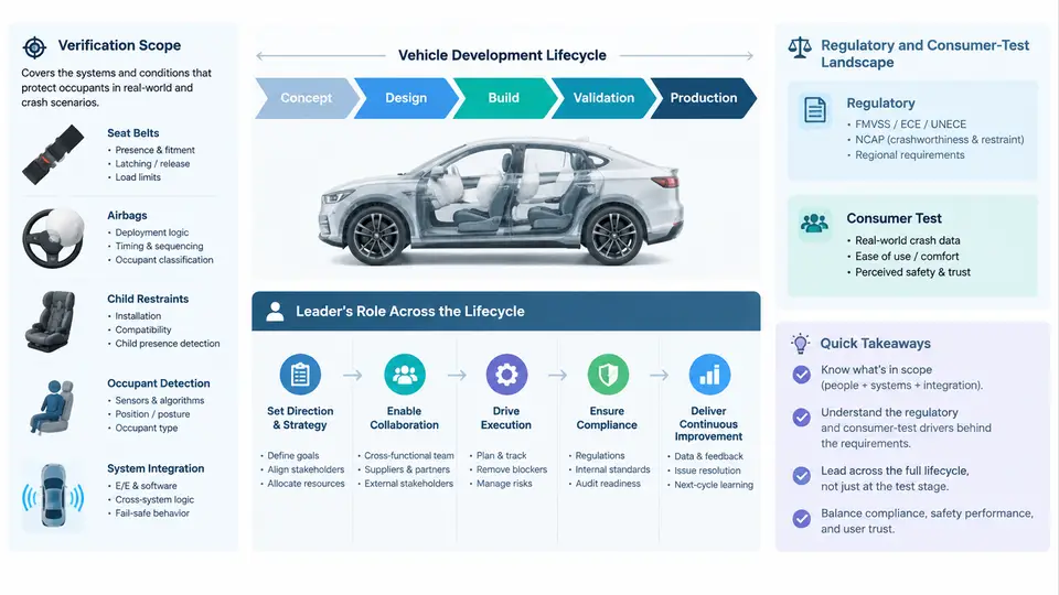
Occupant restraint verification is the discipline of demonstrating, with traceable evidence, that every occupant in every seating position is protected to the level required by regulation, by consumer test programs, and by the manufacturer's own internal targets. A restraint verification program leader owns that demonstration end to end: the scope definition, the test matrix, the evidence chain, the risk register, and the final sign-off package. This chapter establishes the three foundations on which all later work depends — what the program actually covers, which external and internal requirements define "pass," and where the leader must intervene during the vehicle development lifecycle.
1. Defining the Verification Scope
Scope is not a list of tests. It is a structured statement of which occupants, in which configurations, are evaluated against which criteria, using which evidence types. A defensible scope statement answers five questions:
- Occupant population: driver, front passenger, second-row outboard, second-row center, third-row, and any rear-facing or belted-only positions. Each position carries its own dummy family (Hybrid III 50th percentile male, 5th percentile female, 95th percentile male, and where applicable Q-series child dummies such as Q3, Q6, Q10, or the ECE R129 family).
- Impact modes: full frontal rigid barrier, offset deformable barrier (ODB), mobile progressive deformable barrier (MPDB), side movable deformable barrier (MDB), side pole, rear impact, and rollover/roof crush where the restraint system contributes.
- Seat and restraint configurations: seat track position (full forward, design position, full rear), recline angle, head restraint height and backset, belt anchorage geometry, pretensioner and load-limiter settings, airbag deployment stage, and occupant size/position variants.
- Evidence types: physical sled and full-vehicle tests, component bench tests, CAE (LS-DYNA or equivalent explicit solver) correlation runs, and subsystem data such as belt force, spool-out, and pressure traces.
- Boundaries and exclusions: what is explicitly out of scope (for example, pedestrian protection or child seat CRS certification) so that no stakeholder assumes coverage that does not exist.
A practical scope artifact is a position × mode × dummy matrix. For a mid-size SUV with three rows, a first-pass matrix might contain 14 seating positions, 6 impact modes, and 4 dummy families, yielding roughly 60–90 distinct test conditions before configuration variants are applied. The leader's job is to prune this to the minimum set that still proves the requirement, then document the rationale for every exclusion.
2. The Regulatory and Consumer-Test Landscape
Two requirement families drive the program, and they do not always agree. Regulatory requirements are mandatory and binary: pass or fail, with legal consequences. Consumer programs are voluntary but commercially decisive: a star rating directly affects market position. The leader must satisfy both, and where they conflict, must satisfy the stricter one or manage the gap explicitly.
| Requirement family | Representative programs | Typical criteria | Nature |
|---|---|---|---|
| Frontal regulation | FMVSS 208, ECE R94/R137, GB 11551 | HIC, chest deflection, femur load, belt force limits, airbag suppression logic | Mandatory, pass/fail |
| Side regulation | FMVSS 214, ECE R95, GB 20071 | Rib deflection, abdominal force, pelvis acceleration, pole intrusion | Mandatory, pass/fail |
| Consumer frontal | US NCAP, Euro NCAP MPDB/Frontal, C-NCAP, Latin NCAP | Weighted injury scores, star thresholds, compatibility metrics | Voluntary, scored |
| Consumer side | Euro NCAP side MDB/pole, US NCAP side, C-NCAP side | Head, thorax, abdomen, pelvis scores; far-side occupant metrics | Voluntary, scored |
| Child occupant | ECE R129, FMVSS 213, consumer CRS fitment | Q-dummy injury criteria, CRS installation, i-Size compatibility | Mixed |
Three practical realities shape how the leader uses this landscape. First, criteria thresholds differ between programs — a chest deflection that passes FMVSS 208 may still lose points in Euro NCAP. Second, test setups differ — barrier mass, impact speed, and dummy seating procedure vary, so a single physical test rarely satisfies two programs simultaneously. Third, programs evolve on fixed cycles (Euro NCAP updates roughly every three years), so the leader must track the protocol version applicable at the vehicle's launch date, not the version current at program start.
3. The Leader's Role Across the Development Lifecycle
The restraint verification leader is not a test coordinator. The role spans five lifecycle phases, and the nature of intervention changes in each.
Concept and target phase. The leader defines the scope matrix, sets injury targets that satisfy both regulatory limits and consumer star ambitions, maps the applicable protocol versions, and secures budget and facility time. The critical output is a signed scope document that engineering, testing, and management all accept. A common failure here is an optimistic scope that omits far-side or third-row occupants, only to have them added late when a consumer protocol update introduces them.
Design and CAE phase. The leader builds the sled test matrix, oversees CAE model correlation against component and sled data, and drives restraint tuning — pretensioner timing, load-limiter force levels, airbag venting and tether geometry. The leader does not perform the tuning, but owns the decision of when a CAE result is credible enough to commit to hardware. A useful discipline is a correlation gate: the CAE model must reproduce sled-measured belt force and chest deflection within an agreed tolerance (for example, ±10% on peak belt force and ±15% on peak chest deflection) before its predictions are used for design decisions.
Prototype test phase. Physical sled and full-vehicle tests execute. The leader manages the test matrix, validates incoming data against expected signatures, and triages failures. When a test fails, the leader decides whether the cause is a restraint design issue, a build variation, a test setup error, or a dummy instrumentation fault — and directs the response accordingly. This is where the leader's technical judgment has the highest leverage, because a misdiagnosed failure can send the program into weeks of unnecessary redesign.
Validation phase. Confirmatory tests are run against the launch-date protocol, the evidence package is assembled, and the sign-off review is conducted. The leader ensures every scope-matrix condition has a traceable result, every deviation is documented with justification, and every open risk has an owner and a closure plan.
Launch and sustain phase. The leader supports production conformity checks, monitors field data for restraint-related issues, and controls any post-launch changes to restraint components or software calibration. A change to a pretensioner supplier or an airbag inflator curve after launch reopens the verification question, and the leader must decide what re-testing is required.
4. What the Leader Actually Owns
Across all five phases, four artifacts define the leader's ownership:
- The scope matrix — the authoritative list of occupant, mode, and configuration conditions to be verified.
- The risk register — open technical risks with likelihood, impact, mitigation, owner, and closure criteria.
- The evidence chain — every test report, CAE correlation record, and deviation justification, indexed to the scope matrix.
- The gate review package — the consolidated evidence presented at each lifecycle gate to authorize progression.
The remainder of this course builds on these foundations: subsequent chapters address test matrix construction, sled and full-vehicle execution, CAE correlation discipline, failure triage, evidence packaging, and gate review leadership. Every one of them depends on the scope, the requirement landscape, and the lifecycle ownership defined here.