1. Program initiation and governance
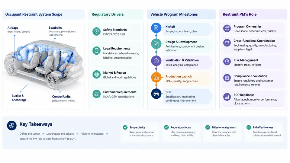
An occupant restraint program does not begin when the first airbag CAD surface is modeled. It begins when someone is formally accountable for a defined scope, a regulatory target set, and a milestone plan that survives contact with the vehicle program. This chapter establishes the governance foundation that every later activity — requirements, CAE, sled testing, supplier management, and launch readiness — depends on.
1.1 What "Occupant Restraint System" Actually Covers
Scope definition is the first governance act because it determines budget, headcount, test matrix, and interface ownership. A complete occupant restraint system (ORS) scope typically includes:
- Frontal restraints: driver and passenger frontal airbags, seat belt pretensioners, load limiters, and buckle pretensioners.
- Side impact restraints: seat-mounted side airbags, curtain airbags (roof rail or sail panel), and far-side airbags.
- Seat belt systems: retractors, webbing, tongue/latch plates, anchorages, height adjusters, and belt reminder hardware.
- Occupant sensing: seat weight sensors (OWS/OCS), buckle switches, seat position sensors, and occupant classification logic.
- Control electronics: the airbag control unit (ACU/SDM), crash sensors, and the restraint wiring harness.
- Child restraint interfaces: ISOFIX/LATCH anchorages and top tether points.
Equally important is what sits outside the ORS scope but interfaces with it: seat structure, steering column, instrument panel, headliner, and body-in-white crush zones. The restraint PM must document these interfaces explicitly, because a late change in seat frame stiffness or IP geometry can invalidate restraint tuning that was already signed off.
1.2 Regulatory and Rating Drivers
Regulatory drivers define the minimum performance envelope and the evidence package. For a global vehicle program, the restraint PM must map each market to its applicable requirements early, because they drive different test configurations, dummy types, and documentation.
| Market / Region | Key Regulation or Rating | Primary Restraint Impact |
|---|---|---|
| United States | FMVSS 208, FMVSS 214, FMVSS 207/210 | Unbelted and belted frontal, side pole, seat anchorage strength |
| Europe | ECE R94/R95, UN R137, Euro NCAP | Offset deformable barrier, side barrier, rating-based scoring |
| China | GB 11551, GB 20071, C-NCAP | Frontal ODB, side MDB, rating protocols |
| Global harmonization | UN R94/R95 mutual recognition | Shared test setup reduces duplicate validation |
Beyond regulation, consumer rating programs (Euro NCAP, C-NCAP, IIHS, NHTSA NCAP) often impose stricter or differently weighted criteria — for example, IIHS side 2.0 uses a heavier moving deformable barrier and higher impact energy than FMVSS 214. The PM should maintain a regulatory driver matrix that lists each requirement, its test condition, the responsible subsystem, and the target milestone for evidence.
1.3 Vehicle Program Milestones and the Restraint Workstream
Restraint development is synchronized to the vehicle program's gate structure. A typical passenger car program uses gates such as:
- Kickoff / Concept (G0–G1): scope freeze, regulatory target set, concept restraint architecture selected.
- Design Freeze / A-surface (G2): airbag module packaging frozen, seat belt routing defined, ACU location fixed.
- Tooling Kickoff (G3): supplier tooling released, first prototype restraint hardware available.
- Engineering Prototype (G4): first full-vehicle crash tests, CAE correlation, tuning iterations.
- Pre-Production / Pilot (G5): production-intent hardware, final calibration, regulatory pre-compliance.
- SOP (G6): all regulatory evidence submitted, PPAP complete, launch calibration locked.
The restraint PM's critical path is usually the calibration loop: CAE → sled → full vehicle → calibration update → re-test. Each loop consumes 6–10 weeks. If the program allows only three loops before G5, the PM must front-load CAE fidelity and supplier hardware availability to avoid a fourth, unscheduled loop.
1.4 The Restraint PM's Role from Kickoff to SOP
The restraint PM is not a passive tracker. The role has five active governance functions:
- Scope boundary owner. Maintain the ORS scope statement and interface register. When seat engineering proposes a frame change at G3, the PM assesses whether it invalidates restraint tuning and triggers a re-test decision.
- Regulatory target owner. Own the regulatory driver matrix. Confirm that every market's requirements are mapped to a test configuration and a responsible engineer. Flag any market where the target is not yet demonstrated.
- Milestone and deliverable tracker. Maintain the restraint workstream plan with entry/exit criteria for each gate. At G2, for example, the exit criterion might be "airbag module envelope frozen and CAE model correlated to within 10% of sled data."
- Interface and dependency manager. Chair the restraint interface meeting. Track open items such as seat belt anchor location, ACU mounting bracket stiffness, and harness routing through the body.
- Risk and escalation owner. Maintain a risk register with probability, impact, and mitigation. Escalate to the program office when a risk threatens a gate exit criterion.
1.5 A Practical Kickoff Deliverable: The Restraint Program Charter
The first tangible output of the PM role is a program charter. A minimal but complete charter for a global B-segment vehicle program might look like this:
RESTRAINT PROGRAM CHARTER — Program: BX21 (example)
Revision: A  |  Date: 2025-01-15  |  PM: [Name]

1. SCOPE
   In scope: frontal airbags (D/P), side airbags (seat + curtain),
   far-side airbag, seat belts with pretensioners and load limiters,
   OCS/OWS, ACU, crash sensors, restraint harness.
   Out of scope: seat structure, steering column, IP, headliner,
   body crush zones (interface only).

2. REGULATORY TARGETS
   US: FMVSS 208 (unbelted + belted), FMVSS 214 (side pole)
   EU: ECE R94, ECE R95, Euro NCAP 2026
   CN: GB 11551, GB 20071, C-NCAP 2024
   Evidence gate: G5 pre-compliance, SOP full submission.

3. MILESTONES
   G0 Kickoff: scope freeze, charter signed
   G1 Concept: architecture selected, reg matrix complete
   G2 Design Freeze: packaging frozen, CAE correlated
   G3 Tooling: supplier tooling released, prototype hardware
   G4 Proto Test: full vehicle crash, calibration loop 1-3
   G5 SOP: final validation, PPAP, regulatory evidence

4. INTERFACES
   Seat structure: frame stiffness, mounting points
   Body: crush zone, B-pillar, roof rail
   Electrical: vehicle network, power supply, ground

5. RISKS
   R1: Seat frame change at G3 -> re-test required (H/H)
   R2: OCS supplier delay -> G4 hardware gap (M/H)
   R3: Euro NCAP protocol update -> target shift (M/M)

6. GOVERNANCE
   Weekly: restraint workstream sync
   Bi-weekly: interface meeting with seat/body/electrical
   Monthly: program office gate review
   Escalation: PM -> Chief Engineer -> Program Director
This charter is deliberately compact. It fits on two pages, but it forces the PM to make scope, regulatory, milestone, interface, and risk decisions explicit before the program accelerates. In practice, the charter is a living document — revised at each gate as scope changes, risks close, and new regulatory information arrives.
1.6 Governance Rhythm and Decision Rights
Governance is not a one-time kickoff event. It is a rhythm. The restraint PM should establish a cadence that matches the program's risk profile:
- Weekly workstream sync: 30 minutes, focused on open actions, blockers, and upcoming deliverables. No status reading — status lives in the tracker.
- Bi-weekly interface meeting: 45 minutes with seat, body, electrical, and supplier representatives. Agenda is the open interface register.
- Monthly gate review: 60 minutes with the program office. The PM presents gate exit criteria status, risk changes, and decisions needed.
Decision rights must be explicit. For example: the PM can approve a calibration change within a defined tolerance band; a change that affects a regulatory test configuration requires chief engineer approval; a scope change requires program director sign-off. Documenting these thresholds prevents both paralysis and unauthorized drift.
1.7 Summary
Program initiation and governance set the trajectory for everything that follows. The restraint PM's first job is to define what the occupant restraint system includes and excludes, map every applicable regulation and rating to a test configuration and owner, align the restraint workstream to the vehicle program's gate structure, and establish a governance rhythm with clear decision rights. The program charter is the tangible artifact that captures these decisions. Get this foundation right, and the later phases — requirements, CAE, sled testing, supplier management, and launch — have a stable frame to build on. Get it wrong, and every subsequent phase inherits the ambiguity.