1. Introduction to occupant restraint engin
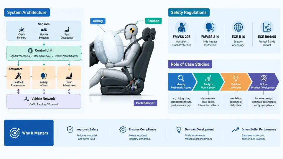
Occupant restraint engineering is the discipline of designing, integrating, and validating the systems that decelerate and position vehicle occupants during a crash so that injury risk stays within acceptable limits. It sits at the intersection of structural crashworthiness, sensing and control, pyrotechnics, materials, ergonomics, and regulatory compliance. A restraint engineer must reason about a complete chain: crash pulse → sensor detection → restraint decision → actuator deployment → occupant kinematics → injury metrics. This chapter establishes the vocabulary and architecture used throughout the course, summarizes the regulatory and consumer-rating landscape, and explains why structured case studies are the primary vehicle for transferring engineering judgment in this field.
1.1 What "Occupant Restraint" Actually Covers
The restraint system is not a single product; it is a coordinated set of energy-management devices and the electronics that decide when and how hard each one acts. The main subsystems are:
- Seat belts and pretensioners — the primary restraint. The belt couples the occupant to the seat and vehicle structure; the pretensioner removes slack within milliseconds, and the load limiter caps belt force to control chest deflection.
- Airbags — frontal driver/passenger, side torso, side curtain, knee, and far-side. Each has a distinct deployment target, fill volume, and venting strategy.
- Seat structures and anti-submarining features — seat pan angle, cushion stiffness, and ramps that prevent the occupant from sliding under the lap belt.
- Airbag control unit (ACU) — accelerometers, safing logic, crash discrimination algorithm, and the firing stage drivers.
- Occupant sensing — seat weight/occupant classification, belt buckle switches, seat position sensors, and rollover sensors that suppress or modulate deployment.
A useful mental model is that the restraint system is a closed-loop, one-shot controller: it senses a crash, classifies it, and fires actuators once, with no opportunity to correct. That single-shot nature is why validation and case-based reasoning matter so much.
1.2 System Architecture and Signal Chain
The architecture can be read as a signal chain from physical event to occupant outcome. Understanding where each element sits helps when diagnosing a deployment anomaly or a rating shortfall.
Two properties of this chain deserve emphasis. First, the timing budget is extremely tight: for a 50 km/h frontal barrier impact, the ACU must decide within roughly 15–30 ms, and the airbag must be fully inflated before the occupant's torso reaches the module, typically 40–60 ms after impact. Second, the chain is coupled: a stiffer load limiter reduces chest deflection but increases head excursion, which can raise HIC against a hard contact. Every design change propagates.
1.3 The Regulatory and Rating Landscape
Restraint design is bounded by mandatory regulation and shaped by consumer ratings. The two serve different purposes and use different test matrices.
| Framework | Type | Representative Tests | Primary Metrics |
|---|---|---|---|
| FMVSS 208 | Mandatory (US) | Frontal rigid barrier 56 km/h; offset deformable barrier; unbelted options | HIC, chest acceleration, femur load, belt geometry |
| FMVSS 214 | Mandatory (US) | Side MDB 54 km/h; pole impact | Rib deflection, abdominal force, pelvic acceleration |
| ECE R94 / R95 | Mandatory (EU) | Offset deformable barrier 56 km/h; side MDB 50 km/h | HIC, chest, abdomen, pelvis |
| Euro NCAP | Consumer rating | Frontal offset, MPDB, side barrier, far-side, whiplash | Weighted score, star rating |
| C-IASI | Consumer rating (China) | 25% small overlap, side pole, roof strength | G/A/M/P grades |
Regulation defines a pass/fail floor; consumer ratings create competitive pressure above that floor. A restraint engineer must therefore design to the union of both, and often to internal targets that are stricter than either, because real-world crashes include configurations no test captures.
1.4 Why Case Studies Drive Product Development
Restraint engineering is not solvable by first-principles calculation alone. The occupant is a complex, variable body; the crash pulse varies with structure and mass; the airbag is a gas-dynamic device with manufacturing tolerances. Simulation (typically LS-DYNA or PAM-CRASH with a validated FE occupant model such as THOR or WorldSID) narrows the design space, but physical sled and full-vehicle tests remain the arbiter. Case studies capture the knowledge that neither equations nor single tests preserve: what went wrong, what was changed, and why the change worked.
A well-structured case study in this course follows a consistent evidentiary pattern, though the emphasis shifts with the problem:
- Configuration — vehicle, restraint content, occupant size (e.g., 50th percentile male Hybrid III), impact mode, and speed.
- Observation — the measured or rated deficiency, with the specific metric and its value (e.g., HIC = 780 against a 700 target).
- Root-cause hypothesis — the mechanism, supported by film review, sensor traces, or CAE correlation.
- Countermeasure — the design change, its parameters, and the trade-offs it introduces.
- Verification — the re-test result and whether the target is met across the required matrix.
1.5 A Worked Orientation Example
Consider a hypothetical frontal offset case used throughout this course as a running example. A mid-size SUV is tested at 64 km/h in a 40% overlap deformable barrier. The 50th percentile male driver records HIC = 720 and peak chest deflection = 42 mm. The internal targets are HIC ≤ 650 and chest deflection ≤ 35 mm. Film shows the head bottoming out on the airbag and then rotating toward the A-pillar.
The engineer's first diagnostic step is to separate the two failure modes. Chest deflection is driven by belt force and the load limiter; head injury is driven by airbag restraint force and head excursion. A plausible first countermeasure is to reduce the load limiter force from 4.0 kN to 3.5 kN, which lowers chest deflection but increases forward excursion. To compensate, the airbag can be made slightly larger or the vent reduced to maintain pressure longer. The trade-off is explicit and must be verified by re-test, not assumed.
Baseline (hypothetical):
  load limiter force   = 4.0 kN
  airbag vent          = 2 x 25 mm
  HIC                  = 720   (target <= 650)
  chest deflection     = 42 mm (target <= 35 mm)

Proposed change:
  load limiter force   = 3.5 kN
  airbag vent          = 2 x 22 mm
  expected effect      = chest deflection down, head excursion up
  verification         = sled re-test + CAE correlation
The point of the example is not the specific numbers — they are illustrative — but the reasoning pattern: identify the metric, identify the mechanism, change a parameter that acts on that mechanism, and predict the side effect before testing.
1.6 How to Use This Course
Each subsequent chapter presents a focused case or technical module. Read the configuration and observation first, form your own hypothesis before reading the countermeasure, and compare your reasoning with the documented one. The goal is not to memorize solutions but to build a repertoire of mechanisms and trade-offs that you can recognize in new problems. Keep the signal chain from Section 1.2 in mind: almost every restraint issue can be located somewhere along it, and locating the problem is half the diagnosis.