1. Program context and scope
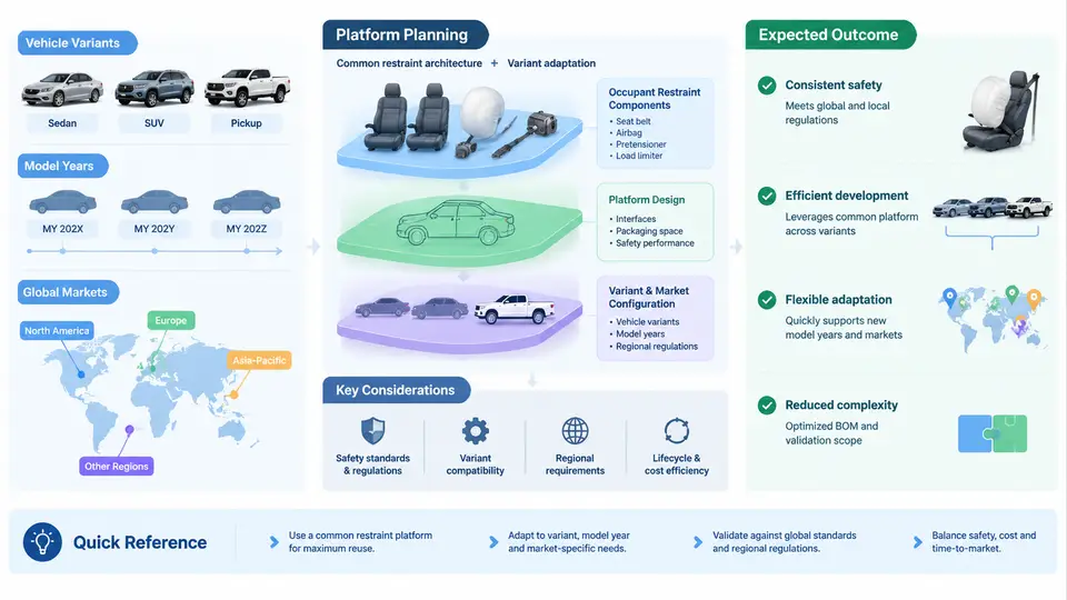
An occupant restraint platform is the coordinated set of airbags, seat belts, pretensioners, load limiters, seat structures, sensors, and the electronic control unit (ECU) calibration logic that together manage occupant kinematics in a crash. When that platform must serve multiple vehicle variants, span several model years, and satisfy regulations across global markets, planning shifts from a single-vehicle design task to a portfolio-level engineering problem. The goal of this chapter is to define what "platform planning" means in that multi-vehicle context, why it is difficult, and how engineering teams structure the work so that one restraint architecture can be reused without compromising safety performance in any single application.
Why a Platform Approach Is Necessary
Vehicle manufacturers rarely develop one restraint system per nameplate. A single vehicle architecture — for example, a unibody crossover platform — typically spawns a short-wheelbase and long-wheelbase variant, multiple powertrain options, several seating configurations (5-seat, 7-seat), and regional derivatives. Each derivative changes mass, stiffness, center of gravity, seat geometry, and occupant packaging. If every derivative received a fully independent restraint design, the cost of validation, tooling, and calibration would scale linearly with variant count, which is commercially unsustainable.
A platform approach instead defines a common restraint architecture — sensor set, ECU family, airbag module interfaces, seat belt anchor strategy — and then manages the delta between variants through calibration and limited hardware changes. The planning problem is to decide, up front, which elements are fixed (common), which are parameterized (calibratable), and which must be variant-specific.
Three Axes of Variation
Multi-vehicle restraint planning must simultaneously manage three independent axes of variation:
- Vehicle variants: body style, wheelbase, mass class, seat count, and seat track position. These affect crash pulse, occupant excursion, and airbag deployment timing.
- Model years: regulatory updates (e.g., FMVSS 208, UN R94/R95, GB 11551), new test dummies (THOR, WorldSID), and incremental hardware changes. A platform must remain compliant across a 5–8 year production life.
- Global markets: different regulatory regimes, belt usage rates, occupant sizes, and seating positions. A platform sold in North America, Europe, and China must satisfy the strictest applicable requirement without over-designing for markets with lighter demands.
These axes interact. A model-year change in one market may force a calibration update that must be re-validated across all variants in all markets. Planning must therefore treat the restraint platform as a configuration-managed system, not a collection of independent designs.
Scope Definition: What Is Inside the Platform Boundary
Before any calibration work begins, the program must define the platform boundary. A typical scope statement for a multi-vehicle restraint platform includes:
| Element | Common (Fixed) | Parameterized | Variant-Specific |
|---|---|---|---|
| ECU hardware family | Yes — single ECU generation | — | — |
| Crash sensor set | Front satellite sensors | Side sensor count/position | Rear sensors for 7-seat |
| Front airbag module | Module interface | Inflator output level | — |
| Seat belt pretensioner | Type (pyrotechnic) | Trigger time | Anchor geometry |
| Calibration dataset | Base logic | Variant coefficients | Market-specific thresholds |
This boundary table is the single most important planning artifact. It forces early decisions about where commonality is achievable and where it is not, and it becomes the basis for the calibration matrix and validation plan.
From Scope to Calibration Matrix
Once the boundary is defined, the planning team builds a calibration matrix: the cross-product of variants, model years, and markets, reduced by eliminating combinations that are not physically produced. For a platform with 4 variants, 3 model years, and 3 markets, the raw cross-product is 36; after eliminating non-existent combinations, a realistic matrix might contain 12–18 distinct calibration datasets.
Each dataset is not a full independent calibration. Instead, the platform uses a layered calibration structure:
- Base logic layer: shared crash detection and deployment decision logic, identical across all variants.
- Variant coefficient layer: mass, stiffness, and geometry-dependent parameters that scale the base logic.
- Market threshold layer: regulatory and usage-based thresholds that adjust deployment aggressiveness.
This layering is what makes the platform economically viable. A change in one market's regulation typically touches only the market threshold layer, not the base logic, which dramatically reduces re-validation scope.
Practical Example: Planning a Crossover Platform
Consider a hypothetical crossover platform with two wheelbases (SWB, LWB), two seat configurations (5-seat, 7-seat), and three markets (North America, Europe, China). The planning team defines the following scope:
- ECU: single hardware generation, two software variants (5-seat, 7-seat).
- Front sensors: common across all variants.
- Side sensors: SWB uses 2 per side; LWB uses 3 per side to cover the longer cabin.
- Front airbag: common module, two inflator output levels (standard, high-output for heavier LWB).
- Calibration: 6 base datasets (2 wheelbase × 3 market), with 7-seat derivatives sharing the base dataset plus a seat-occupancy parameter set.
The resulting calibration matrix has 6 primary datasets and 2 derivative parameter sets, rather than 12 independent calibrations. Validation testing is planned against the worst-case combination for each requirement: heaviest variant for frontal pulse, longest cabin for side curtain coverage, and strictest market for deployment thresholds.
Key Planning Decisions and Their Consequences
Three decisions dominate platform planning:
- Sensor set commonality: Sharing sensors reduces cost but may force compromises in deployment timing for extreme variants. The planning team must verify that the common sensor set can still discriminate crash severity across the mass range.
- Calibration layering depth: More layers increase flexibility but also increase the number of datasets to validate. A practical rule is to keep layers to three or fewer unless a regulatory driver justifies more.
- Validation strategy: Full validation of every combination is prohibitively expensive. Instead, the plan identifies representative worst-case configurations and uses engineering judgment plus simulation to cover the remaining combinations.
Visualizing the Platform Planning Structure
The following diagram shows how the three axes of variation feed into the layered calibration structure and the resulting validation scope. It illustrates the relationship between scope definition, calibration layering, and the reduced validation matrix.
What This Chapter Establishes
This chapter has defined the program context for multi-vehicle occupant restraint platform planning: the three axes of variation (variants, model years, markets), the scope boundary that separates common from variant-specific elements, and the layered calibration structure that makes platform reuse economically and technically feasible. The calibration matrix and validation strategy introduced here become the foundation for the detailed planning activities in subsequent chapters, including sensor set definition, deployment logic design, and regulatory compliance mapping.
The key takeaway is that platform planning is not a single design task but a configuration management discipline. The planning team's primary deliverable is not a calibration dataset but a structured plan that defines what is common, what is parameterized, and how the resulting combinations will be validated — with the explicit understanding that this plan will be revisited as model years and market requirements evolve.