1. Seatbelt program lifecycle overview
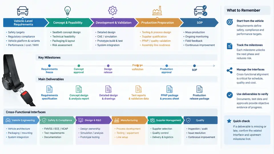
A seatbelt program is not a single engineering task; it is a multi-year, cross-functional development chain that begins with vehicle-level occupant safety targets and ends with Start of Production (SOP). Program managers must understand where each activity sits in that chain, which milestone gates it, and which functions own the interfaces. This chapter maps the full lifecycle, the key milestones, the deliverables tied to each gate, and the cross-functional interfaces that keep the program synchronized.
1.1 The Lifecycle at a Glance
A typical seatbelt program runs roughly 30–42 months from vehicle program kickoff to SOP, depending on platform carryover. The lifecycle is usually divided into five phases:
- Concept & Target Setting — vehicle-level requirements are decomposed into system and component targets.
- Design & Development — geometry, restraint performance, and supplier selection mature through iterative CAE and physical testing.
- Validation — full-scale crash, sled, and component tests confirm compliance with regulatory and internal requirements.
- Industrialization — tooling, PPAP, and line trials prepare the plant for volume production.
- SOP & Launch Support — production starts, and the team supports ramp-up and early field feedback.
Each phase is bounded by a milestone gate. Passing a gate requires a defined deliverable set and sign-off from the responsible functions. The program manager's core job is to keep these gates on schedule and to resolve interface conflicts before they become gate blockers.
1.2 Vehicle-Level Requirements as the Starting Point
Everything begins with the vehicle-level requirement document, often called the Vehicle Technical Specification (VTS) or Vehicle Requirements Specification. For seatbelts, the VTS typically includes:
- Regulatory targets: FMVSS 208, FMVSS 209, FMVSS 210, ECE R16, ECE R14, and market-specific variants.
- Consumer rating targets: US NCAP, Euro NCAP, C-NCAP star and score objectives.
- Occupant injury criteria: HIC, chest deflection, femur load, neck injury (Nij), and submarining limits.
- Packaging constraints: B-pillar geometry, seat structure interface, retractor mounting envelope.
- Comfort and ergonomics: pull-out force, retraction force, tongue presentation, height adjuster range.
- Durability and environmental: temperature cycling, dust, salt spray, abrasion cycles.
These vehicle-level targets are decomposed into system-level requirements for the seatbelt system, then into component-level specifications for webbing, retractor, buckle, pretensioner, and load limiter. This decomposition is the first major cross-functional interface: the safety attribute team owns the vehicle targets, the seatbelt system engineer owns the system specification, and the supplier owns the component specification.
1.3 Key Milestones and Their Deliverables
While milestone names vary by OEM, the following gate structure is widely used. The table below summarizes the typical milestones, their timing relative to SOP, and the primary deliverables.
| Milestone | Timing (months before SOP) | Primary Deliverables | Gate Owner |
|---|---|---|---|
| Program Kickoff / G0 | 36–42 | Vehicle targets, program timing, preliminary packaging study | Vehicle Program Manager |
| Concept Freeze / G1 | 30–34 | System concept, supplier nomination, CAE concept correlation | Safety Attribute Lead |
| Design Freeze / G2 | 22–26 | Released 3D/2D data, DFMEA, DVP&R, first prototype build | Seatbelt System Engineer |
| Validation Complete / G3 | 12–16 | Full-scale crash results, sled matrix, component validation reports | Validation Manager |
| Production Readiness / G4 | 4–8 | PPAP, tooling sign-off, line trial results, control plan | Manufacturing Engineer |
| SOP / G5 | 0 | Production part approval, launch readiness review, safe launch plan | Plant Launch Manager |
Each gate has entry and exit criteria. For example, G2 (Design Freeze) cannot be passed until the DFMEA is complete, the DVP&R is approved, and the first prototype build has demonstrated that the design meets packaging and basic functional requirements. The program manager tracks these criteria in a gate review checklist and escalates any open item that threatens the gate date.
1.4 Cross-Functional Interfaces
A seatbelt program touches nearly every function in the vehicle development organization. The most critical interfaces are:
- Safety Attribute — owns vehicle-level injury targets and signs off on restraint performance.
- Body & Interior Engineering — owns B-pillar, seat structure, and trim interfaces; provides mounting points and routing space.
- Seat Engineering — owns seat frame, cushion, and backrest; the seatbelt buckle and pretensioner often mount to the seat.
- Electrical & Electronics — owns buckle switch signal, pretensioner firing circuit, and occupant classification system integration.
- Purchasing & Supplier Quality — manages supplier nomination, cost, and PPAP.
- Manufacturing & Plant — owns assembly sequence, torque strategy, and line trial execution.
- Validation & Test Operations — owns sled, crash, and component test execution.
- Homologation & Regulatory — owns type approval and market-specific compliance.
Interface failures are a leading cause of program delays. A common example: the seatbelt retractor mounting point on the B-pillar is defined by Body Engineering, but the retractor envelope is defined by the seatbelt supplier. If the two are not synchronized at G1, the retractor may not fit at G2, forcing a late B-pillar change that cascades into trim, welding, and paint. The program manager must ensure that interface requirements are documented in an Interface Control Document (ICD) and reviewed at every gate.
1.5 Practical Example: Tracing a Requirement Through the Lifecycle
Consider a vehicle-level requirement: "Front occupant chest deflection shall not exceed 42 mm in the 56 km/h full-frontal rigid barrier test." This requirement is decomposed as follows:
- System level: The seatbelt system must provide a load-limiting force of 3.5–4.5 kN at the retractor, with a pretensioner stroke of at least 60 mm.
- Component level: The load limiter torsion bar must have a yield torque of 2.8–3.2 N·m, and the webbing must have an elongation of 7–9% at 10 kN.
- Validation: A sled test at 56 km/h with a 50th percentile male dummy must demonstrate chest deflection ≤ 42 mm. The DVP&R lists this as test case SL-03, with a sample size of 3 and a pass/fail criterion of all three ≤ 42 mm.
- Industrialization: The torsion bar supplier must demonstrate process capability (Cpk ≥ 1.67) for yield torque, and the plant must verify torque at the retractor assembly station every 2 hours.
If the sled test at G3 returns a chest deflection of 45 mm, the program manager must trigger a cross-functional review. The safety attribute team may request a lower load limiter force, which changes the component specification, which requires a supplier change, which may affect the G4 PPAP timing. This is the essence of program management: understanding how a change in one requirement propagates through the lifecycle and across interfaces.
1.6 Common Pitfalls and How to Avoid Them
- Late supplier nomination: If the seatbelt supplier is not nominated by G1, the design freeze at G2 will be based on incomplete supplier data. Mitigation: start supplier technical reviews during concept phase.
- Unclear interface ownership: When the B-pillar mounting point is owned by Body but the retractor envelope by the supplier, neither party may own the fit check. Mitigation: document every interface in the ICD with a single owner.
- Validation matrix gaps: If the DVP&R does not cover a market-specific regulatory variant, homologation may fail after G3. Mitigation: review the DVP&R against all target markets at G2.
- PPAP delays: If tooling is not ready at G4, SOP slips. Mitigation: track tooling lead times from G2 and conduct early line trials.
With the lifecycle map in place, subsequent chapters will drill into each phase: requirement decomposition, design and CAE, validation planning, supplier management, and industrialization. The key takeaway from this chapter is that a seatbelt program is a chain of interdependent gates and interfaces; the program manager's value lies in keeping that chain synchronized from vehicle-level targets to SOP.