1. Program leadership foundations
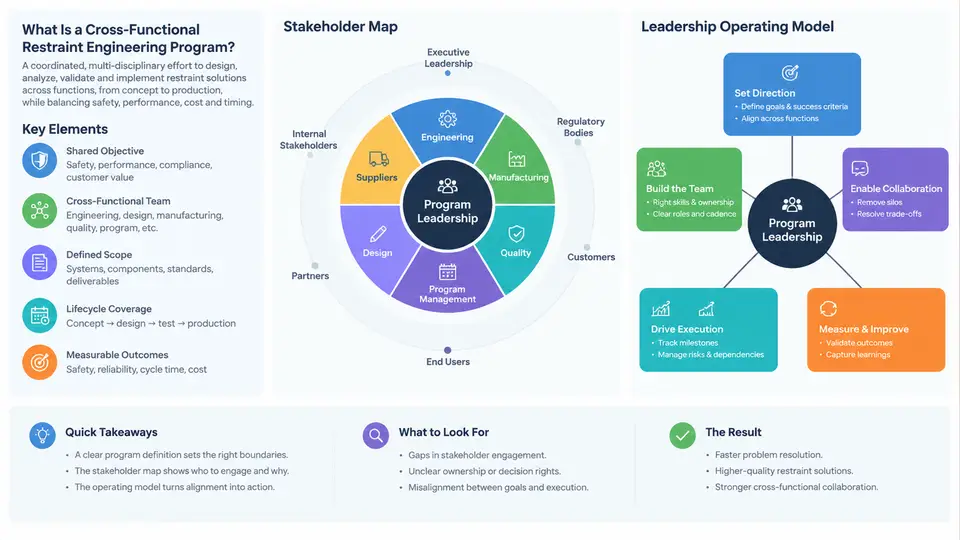
A cross-functional restraint engineering program is a coordinated, time-bounded effort to deliver a restraint system — seat belts, airbags, pretensioners, load limiters, anchors, and the sensing/control logic that triggers them — that satisfies regulatory, consumer-rating, and internal performance targets across multiple vehicle platforms. What makes it a program rather than a project is the deliberate integration of engineering disciplines that normally operate on different clocks: occupant safety CAE runs in weeks, restraint ECU software releases in months, supplier tooling lead times run into quarters, and homologation testing is gated by regulatory calendars. The program leader's job is to keep those clocks synchronized against a single set of performance commitments.
Three properties distinguish a restraint program from adjacent engineering work. First, it is safety-critical and evidence-bound: every claim about occupant performance must trace to a physical or validated CAE result, and the evidence chain is auditable. Second, it is interface-dense: the restraint system touches body structure, seats, electrical architecture, interior trim, and the vehicle's crash sensing strategy. Third, it is regulated at the outcome level — FMVSS 208, FMVSS 209/210, ECE R16/R94/R95, and consumer protocols such as Euro NCAP and US NCAP define pass/fail in terms of occupant response, not component behavior. A program leader who manages only component delivery will fail; the deliverable is occupant outcome under defined test conditions.
Stakeholder Map: Who Actually Controls the Outcome
Restraint programs fail more often from unmanaged interfaces than from weak analysis. A useful stakeholder map separates decision authority from technical contribution and from gate authority, because these three roles are frequently held by different people.
| Stakeholder | Primary contribution | Authority / gate role | Typical failure mode if unmanaged |
|---|---|---|---|
| Program Manager (vehicle) | Timing, budget, platform trade-offs | Approves scope and schedule changes | Restraint slips silently behind vehicle milestones |
| Restraint System Lead | System architecture, performance allocation | Owns system-level DVP&R | Component specs drift from system targets |
| Body Structure Engineering | Crash pulse, intrusion, anchor stiffness | Owns BIW CAE correlation | Pulse changes invalidate restraint tuning late |
| Seat Engineering | Seat structure, track strength, occupant position | Owns seat-level compliance | Seat back deflection alters occupant kinematics |
| Electrical / E/E Architecture | Power, ground, bus, diagnostics | Owns network and power release | Deployment loop latency or brownout at crash |
| Restraint ECU Supplier | Calibration, algorithm, diagnostics | Owns software release content | Calibration freeze misses vehicle build dates |
| Homologation / Compliance | Regulatory interpretation, witness testing | Signs off regulatory submissions | Test matrix gaps discovered after tooling is cut |
| Manufacturing / Plant | Buildability, torque, traceability | Owns process capability sign-off | Anchor torque variance degrades repeatability |
The map is not an org chart. It is a dependency map: it tells the program leader where a change in one area propagates. For example, a 15 mm change in seat track position moves the occupant reference point, which shifts airbag stand-off distance, which changes the required inflator output, which changes the deployment pressure curve, which may push the ECU calibration outside its validated envelope. One geometry decision, five downstream consequences.
The Leadership Operating Model
An operating model is the repeatable mechanism by which the program makes and records decisions. For restraint programs, four elements are non-negotiable.
1. A single performance baseline. All disciplines work to one documented set of occupant targets and test conditions — barrier type, impact speed, occupant size (e.g., 5th percentile female, 50th percentile male, 95th percentile male), seat position, and belt usage state. When CAE, sled, and vehicle teams use different baselines, results cannot be compared and the program loses its ability to converge.
2. A gated evidence chain. Each phase advances only when its evidence is complete: component-level (inflator tank tests, buckle strength, webbing elongation), subsystem-level (sled tests with body-in-white pulse), and full-vehicle level (barrier and pole tests). The program leader enforces that a subsystem gate is not passed using component evidence alone.
3. A change-control loop with explicit propagation review. Every engineering change request (ECR) affecting geometry, mass, pulse, or electrical interface must be reviewed for restraint impact before approval. The review asks three questions: does it change occupant position, does it change crash pulse, does it change deployment timing?
4. A risk register tied to test events. Risks are not abstract. Each entry names the specific test that would reveal the problem, the date that test occurs, and the mitigation if it fails. This converts risk management from a document exercise into a scheduling instrument.
How the Operating Model Behaves in Practice
The model is best understood as a signal path: inputs (requirements, geometry, pulse) flow through discipline-specific work, converge at integration gates, and produce occupant outcomes that feed back as calibration adjustments. The diagram below shows this structure, including where the program leader intervenes.
Making the Model Operational
Two mechanisms turn the operating model from a diagram into daily practice. The first is a weekly interface review with a fixed agenda: open change requests and their propagation status, gate readiness for the next 30 days, and any test result that deviates from the baseline by more than the agreed tolerance. The second is a decision log that records, for each significant choice, the alternatives considered, the evidence used, the owner, and the date. When a homologation witness asks why a particular inflator output was selected, the answer is in the log, not in someone's memory.
With the program defined, the stakeholders mapped, and the operating model established, the remaining chapters build the technical and managerial depth: performance allocation, CAE-to-test correlation, supplier integration, calibration governance, and homologation execution. Each of those depends on the foundation set here — one baseline, one evidence chain, one change-control loop, and one risk register bound to real test events.