1. Automotive structures as physics problem
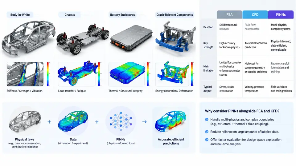
An automotive body is not a single object but a hierarchy of load-carrying systems, each governed by a different dominant physics. Before asking whether a physics-informed neural network (PINN) is the right tool, we must first describe these systems as well-posed boundary-value problems: what is the domain, what are the governing equations, what are the boundary and loading conditions, and what quantity do we actually need to predict?
Consider four representative subsystems that dominate modern vehicle development.
Body-in-White (BIW)
The body-in-white is the welded sheet-metal skeleton before paint and trim. It is a thin-walled assembly of stamped panels — floor, rockers, A/B/C pillars, roof rails, shock towers, and longitudinal rails — joined by thousands of spot welds and structural adhesives. Mechanically, BIW is a large-displacement, elasto-plastic shell structure. Its governing description is the momentum balance
rho * d2u/dt2 = div(sigma) + f_body
sigma = C : (epsilon - epsilon_p)
epsilon = 0.5 * (grad(u) + grad(u)^T)
with shell kinematics reducing the 3D problem to a midsurface plus thickness. The quantities engineers care about are global torsional and bending stiffness (typically reported in N·m/deg and N/mm), the first 10–20 natural frequencies, and local stress concentrations near joints. A typical BIW torsional load case applies equal and opposite vertical forces at the front shock towers while the rear suspension pickup points are constrained — a classic free-free or constrained-free setup whose stiffness target might be, for example, 25,000 N·m/deg for a mid-size sedan.
Chassis and Suspension Components
Control arms, subframes, knuckles, and stabilizer bars carry combined bending, torsion, and multiaxial fatigue loading. Here the physics is high-cycle fatigue under variable amplitude spectra, often described by a rainflow-counted load history and a Basquin or Coffin–Manson relation. The design question is rarely "what is the stress now?" but "how many cycles until crack initiation?" — a question that couples structural dynamics with material degradation.
Battery Enclosures
Battery packs introduce a multiphysics problem. The enclosure must provide structural crash protection, but it also manages thermal load from cell operation and, in thermal runaway, from exothermic decomposition. The governing equations span structural dynamics, heat conduction, and sometimes fluid flow for cooling plates:
rho * cp * dT/dt = div(k * grad(T)) + Q_cell + Q_runawayDesign targets include intrusion limits (e.g., < 5 mm into the module volume under a 50 km/h side pole impact), modal separation from road excitation, and thermal propagation delay between adjacent cells.
Crash-Relevant Components
Crash boxes, bumpers, and B-pillars are designed to absorb energy through controlled plastic folding. The physics is highly nonlinear: large strain, strain-rate sensitivity, contact, and self-folding. The output of interest is the force–displacement curve and its integral, the absorbed energy, plus the peak deceleration transmitted to occupants.
Why PINNs Alongside FEA and CFD
Finite element analysis discretizes the domain into elements and solves the weak form. It is mature, verified, and the industry standard. But it has known costs: mesh generation for complex BIW can take days; a full vehicle crash model may contain 10–20 million elements and run for hours on a cluster; and every design change requires a new mesh and a new solve. CFD for battery thermal management faces similar meshing and turnaround burdens.
PINNs offer a different trade. They approximate the solution as a neural network u_theta(x, t) and train by minimizing a composite loss:
L = L_PDE + lambda_bc * L_BC + lambda_ic * L_IC + lambda_data * L_data
L_PDE = mean( (N[u_theta] - f)^2 )   over collocation points
where N is the differential operator. The advantages are mesh-free evaluation, natural handling of inverse problems (estimating unknown material parameters from sparse sensor data), and the ability to fuse measurement data with physical laws. The disadvantages are equally real: training can be slow, convergence for stiff or highly nonlinear problems is not guaranteed, and accuracy near sharp gradients — exactly where crash and joint stresses live — remains an active research challenge.
The practical stance for automotive structures is therefore complementary, not replacement. Use FEA where the geometry is fixed and a high-fidelity answer is needed once. Use PINNs where you need many fast evaluations, where sensor data must be assimilated, or where the parameter space is too large for repeated meshing. The table below summarizes the mapping.
| Subsystem | Dominant Physics | Typical Output | PINN Suitability |
|---|---|---|---|
| BIW | Elasto-plastic shells, modal | Stiffness, frequencies | Moderate — inverse material ID |
| Chassis | Fatigue, multiaxial | Cycles to initiation | High — data fusion |
| Battery enclosure | Thermo-mechanical | Temperature, intrusion | High — multiphysics |
| Crash components | Nonlinear dynamics, contact | Force–displacement | Emerging — sharp gradients |
The map above is not a claim that PINNs solve all four subsystems today. It is a decision aid: identify the dominant physics, the required output, and the cost of repeated FEA/CFD solves. Where the cost is high and data exist, a PINN is worth prototyping. Where the geometry is fixed and a single high-fidelity answer suffices, FEA remains the correct choice.
In the chapters that follow, we will formalize the PINN loss for each of these subsystems, examine how to encode boundary conditions for shell and solid domains, and study where the method succeeds and where it still requires hybrid FEA–PINN workflows.