1. Restraint calibration in safety-critical
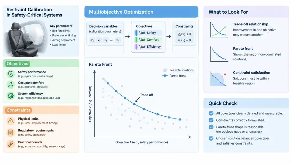
Restraint systems — seat belts with pretensioners and load limiters, airbag inflators, and the occupant-sensing logic that decides when they fire — are among the few automotive subsystems whose failure modes are measured in human lives. Calibrating them means choosing dozens of coupled parameters so that the system performs acceptably across a wide envelope of crash severities, occupant sizes, seating positions, and impact directions. No single setting is optimal for every scenario, and improvements in one metric routinely degrade another. This chapter establishes the vocabulary and the mathematical structure we will use for the rest of the course: what we are optimizing, what we are forbidden to violate, and how the calibration task becomes a formal multiobjective optimization problem.
What "Calibration" Actually Means Here
A restraint calibration is a vector of tunable parameters, not a single number. Typical decision variables include:
- Pretensioner trigger time
t_pt(ms after impact), often per belt anchor. - Load limiter force level
F_ll(kN), sometimes a two-stage profile with a switch time. - Airbag inflator output — mass flow rate or a dual-stage split between primary and secondary charges.
- Vent size / pressure relief governing bag stiffness during the ride-down phase.
- Occupant classification thresholds that gate deployment level (e.g., low-risk vs. full-power).
These variables interact strongly. Advancing t_pt reduces belt slack and chest excursion, but if it fires too early relative to the occupant's forward motion it can pull the torso into the deploying bag. Raising F_ll limits chest deflection but increases head forward travel and the risk of head contact with the steering wheel. The calibration engineer is therefore never tuning one parameter; they are navigating a coupled response surface.
Objectives: What We Are Trying to Minimize
Injury risk is quantified through standardized criteria measured on instrumented Anthropomorphic Test Devices (ATDs) and, increasingly, on human body models. The most common objective functions are:
| Metric | Symbol | Typical threshold | Physical meaning |
|---|---|---|---|
| Head Injury Criterion | HIC15 | ≤ 700 | Resultant head acceleration over a 15 ms window |
| Chest deflection | Dchest | ≤ 42 mm | Rib cage compression |
| Chest acceleration (3 ms clip) | A3ms | ≤ 60 g | Sustained chest deceleration |
| Neck injury criterion | Nij | ≤ 1.0 | Combined axial force and bending moment |
| Femur axial force | Ffemur | ≤ 10 kN | Knee-thigh-hip load path |
Each metric is evaluated across a load case matrix: frontal rigid barrier at 25 and 35 mph, offset deformable barrier, oblique moving deformable barrier, and out-of-position (OOP) static deployments. A calibration is only meaningful if it is assessed over this whole matrix, because a setting that minimizes HIC in a 35 mph full-frontal test may produce unacceptable chest deflection in a 25 mph offset impact.
This is the crux: we do not have one objective. We have a vector of objectives, one per metric per load case, and they conflict. Formally, for a decision vector x ∈ ℝn and a set of load cases c ∈ C, we seek:
minimize  F(x) = [ f_1(x), f_2(x), ..., f_m(x) ]
where     f_k(x) = injury metric k evaluated over load case matrix
subject to g_j(x) ≤ 0   (regulatory and physical constraints)
           x_L ≤ x ≤ x_U  (parameter bounds)
Because the objectives conflict, there is generally no single x that minimizes all fk simultaneously. The solution is a Pareto set: the collection of calibrations where no objective can be improved without worsening another. The engineer's job is to select a preferred point from that set based on program priorities and regulatory margins.
Constraints: The Non-Negotiable Boundaries
Constraints fall into three families, and confusing them with objectives is a common and costly error.
- Regulatory constraints (hard). FMVSS 208, ECE R94/R95, and similar standards define pass/fail limits. A calibration that violates HIC 700 is not "suboptimal" — it is non-compliant and cannot ship. These are inequality constraints, not objectives.
- Physical and packaging constraints. Inflator output cannot exceed the module's structural rating; pretensioner stroke is bounded by belt geometry; vent area is limited by bag pattern. These appear as parameter bounds
x_L ≤ x ≤ x_U. - Robustness constraints. The calibration must hold across manufacturing tolerances, temperature extremes (−35 °C to +85 °C), and occupant mass variation. A point that passes only at nominal conditions is fragile. We typically require the constraint to hold for the worst case over a tolerance box, which converts a deterministic constraint into a min-max or chance constraint.
Why This Is Genuinely Multiobjective
Three properties make restraint calibration a textbook multiobjective problem rather than a disguised single-objective one:
- Non-commensurable units. HIC is dimensionless, deflection is in millimeters, force is in kilonewtons. There is no physically meaningful exchange rate between them.
- Conflicting gradients. Reducing chest deflection via a stiffer load limiter increases head travel; the two objectives have opposing sensitivities to the same variable.
- Discontinuous, noisy responses. Deployment is a threshold event. Small changes in trigger time can flip a bag from "just in time" to "out of position," producing step changes in the response surface that gradient-based methods handle poorly.
The figure below shows the structural relationship between the decision variables, the simulation/experiment pipeline, the objective vector, and the constraint gate that separates feasible from infeasible calibrations.
A Concrete Formulation Example
To make this tangible, consider a simplified frontal calibration with three decision variables and two load cases. Suppose we fix the inflator and vent, and tune only t_pt, F_ll, and a secondary-stage delay t_2. A representative formulation might be:
Decision variables:
  t_pt  ∈ [10, 30] ms
  F_ll  ∈ [2.0, 4.5] kN
  t_2   ∈ [0, 40] ms

Objectives (all minimized):
  f1 = HIC15  (35 mph frontal)
  f2 = D_chest (35 mph frontal)
  f3 = HIC15  (25 mph offset)
  f4 = D_chest (25 mph offset)

Constraints:
  HIC15 ≤ 700        for all load cases
  D_chest ≤ 42 mm    for all load cases
  N_ij ≤ 1.0         for all load cases
  t_pt + t_2 ≤ 55 ms (inflator timing window)
Running a design-of-experiments sweep over this space (e.g., a Latin hypercube of 200 points, each evaluated with an FE occupant model) produces a cloud of feasible and infeasible calibrations. The feasible subset is then filtered for non-dominance to approximate the Pareto front. In practice, engineers often find that the front is steeply curved: the first few millimeters of chest deflection reduction are cheap, but pushing below ~35 mm forces a large HIC penalty. That curvature is the real decision-making information, and it is invisible if you collapse the problem into a single weighted score.
Key Takeaways for the Rest of the Course
Restraint calibration is a constrained multiobjective optimization problem over a coupled parameter vector, evaluated across a load case matrix, with hard regulatory limits that must never be traded against performance metrics. The objectives are non-commensurable and conflicting, so the meaningful output is a Pareto set rather than a single optimum. Every subsequent chapter builds on this structure: surrogate modeling to make the evaluation affordable, evolutionary and Bayesian algorithms to approximate the Pareto front, robustness handling to keep constraints satisfied under uncertainty, and decision-support methods to select a final calibration from the front.