1. Generative design for automotive energy
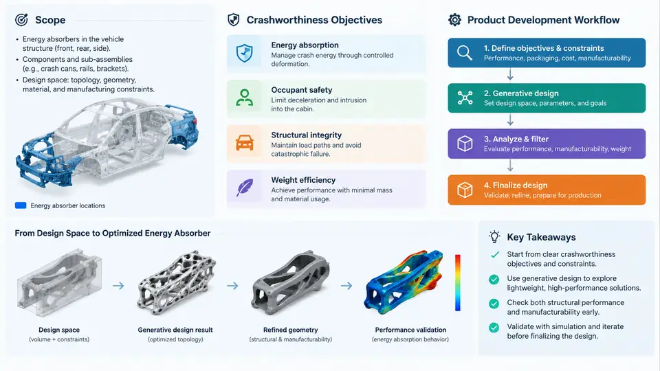
An automotive energy absorber is a sacrificial structure whose job is to convert kinetic energy into controlled plastic deformation during a crash, while limiting the peak force transmitted to occupants and protected subsystems. Typical examples include front bumper crash boxes, rear rails, side sill inserts, battery-pack side guards, and underbody intrusion beams. Generative design enters this domain because these parts sit at the intersection of conflicting requirements: they must be stiff enough for stiffness-driven load cases, weak enough in a controlled way to crush progressively, light enough to reduce mass, and manufacturable at production volume. This chapter defines what generative design covers in this context, which crashworthiness objectives it must satisfy, and how the work is sequenced inside a real product development workflow.
Scope: What Generative Design Does and Does Not Cover
In this course, generative design means a computational process that explores a large design space under explicit constraints and objectives, then returns a set of candidate geometries that are subsequently validated by high-fidelity simulation and physical testing. It is not a single algorithm. The scope includes topology optimization, lattice and shell infill generation, multi-material distribution, and shape or bead optimization, all driven by crash-relevant load cases.
Three boundaries matter. First, generative design produces candidates, not certified parts. A candidate must still pass explicit finite element (FE) verification and physical validation. Second, the process is only as good as its load cases and constraints; a generator given a static bending case will not spontaneously produce a progressive folding mode. Third, generative design does not replace material characterization. The strain-rate-dependent behavior of the chosen alloy or composite governs whether a candidate is realistic, so material data is an input, not an afterthought.
Crashworthiness Objectives for Energy Absorbers
Crashworthiness objectives are usually expressed as a small set of quantitative targets derived from regulation, consumer rating programs, and internal targets. For an energy absorber, the most common objectives are:
- Specific Energy Absorption (SEA) — energy absorbed per unit mass, typically in kJ/kg. Higher is better, but only if the crush mode remains stable.
- Peak Crushing Force (PCF) — the initial force spike. It must stay below a threshold set by the occupant or subsystem it protects.
- Mean Crushing Force (MCF) — the average force over the crush distance. A high MCF with a low PCF indicates an efficient, progressive absorber.
- Crush Force Efficiency (CFE) — the ratio MCF/PCF. Values near 1.0 indicate a flat, stable force–displacement curve; typical steel crash boxes reach roughly 0.6–0.8.
- Intrusion and stroke — the available crush distance must be fully used without bottoming out or fracturing.
- Mode stability — the absorber must fold progressively rather than split, buckle globally, or rotate.
These objectives conflict. Increasing wall thickness raises MCF and SEA but also raises PCF and mass. Adding triggers or beads lowers PCF and stabilizes the mode but can reduce SEA if over-applied. Generative design is valuable precisely because it can search this trade-off space rather than requiring the engineer to guess a single geometry.
From Objectives to a Design Space
Before any generation run, the engineer defines a design space: the maximum envelope the part may occupy, the non-design regions (mounting points, fastener bosses, interfaces to adjacent rails), and the load cases. A representative setup for a front crash box might use:
Design space: 120 mm x 80 mm x 200 mm envelope
Non-design: rear mounting flange (20 mm), front bumper interface (15 mm)
Material: AA6061-T6 extrusion, strain-rate data at 0.001 / 1 / 100 / 1000 s^-1
Load case 1: frontal impact, 15 m/s, 60 kg impactor, 150 mm stroke
Load case 2: 30-degree offset, 12 m/s, 60 kg impactor
Load case 3: static bending, 5 kN lateral, stiffness target
Objective: maximize SEA, minimize PCF, subject to mass <= 1.2 kg
Constraint: minimum wall thickness 1.5 mm, extrusion draw direction along X
The load cases are not decorative. A generator that only sees the frontal case will often produce a geometry that fails the offset case, because the offset case introduces bending and torsion that the frontal case does not. Including both from the start is cheaper than repairing a candidate later.
The Product Development Workflow
The workflow below is the sequence this course follows. It is iterative, not linear: results from validation feed back into the design space definition.
Each stage produces a specific artifact. Requirements produce a target table. Design space produces a CAD envelope and a load-case deck. Material model produces a validated constitutive card. The generation run produces a candidate set. The candidate filter reduces that set using the objective metrics. FE verification confirms the survivors. Physical test confirms the final choice. Design release freezes the geometry and its manufacturing data.
How the Stages Interact in Practice
The most common failure in this workflow is treating it as a one-way pipeline. In reality, the candidate filter often reveals that the design space was too restrictive — for example, every candidate exceeds the PCF target because the non-design flange is too stiff. The correct response is to revisit the design space, not to accept a poor candidate. Similarly, if FE verification shows a global buckling mode that the generator did not predict, the load cases or the mode-stability constraint need revision.
A second practical point concerns mesh and solver settings. Explicit crash simulations are sensitive to element size, hourglass control, and contact definitions. A candidate that looks excellent at a coarse mesh may lose its progressive fold at a finer mesh. The verification stage should therefore include a mesh convergence check on the force–displacement curve, not just a single run.
What a Good Outcome Looks Like
A successful generative design outcome for an energy absorber is not simply the lightest part. It is a part that:
- Meets or exceeds the SEA target while staying under the mass budget.
- Keeps PCF below the threshold across all specified load cases, not just the frontal one.
- Shows a stable, progressive force–displacement curve with CFE in the expected range.
- Can be manufactured by the intended process — extrusion, stamping, casting, or additive — without violating draw direction, minimum thickness, or tooling constraints.
- Has been verified by FE and confirmed by at least one physical test before release.
The rest of this course builds on this foundation. Subsequent chapters will go deeper into each stage: how to formulate crash load cases, how to set up generation runs for different manufacturing processes, how to interpret force–displacement curves, and how to close the loop between simulation and test. The workflow above is the backbone that connects them.