1. Vehicle-level occupant restraint system
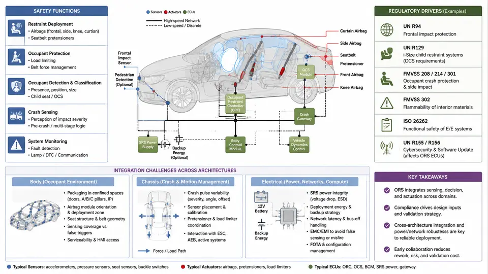
An occupant restraint system is not a single product but a distributed safety function that spans the body structure, the chassis, and the electrical/electronic (E/E) architecture. At vehicle level, its purpose is to manage occupant kinematics during a crash event so that injury metrics stay within regulated and consumer-rating limits. This chapter establishes the system boundary, the safety functions it must deliver, the regulatory and rating drivers that shape its design, and the integration challenges that appear when restraint requirements propagate across body, chassis, and electrical domains.
Safety Functions and the Restraint Chain
The restraint system can be decomposed into four functional layers that operate in sequence within a few tens of milliseconds:
- Crash sensing and discrimination — accelerometers, pressure satellites, and roll-rate sensors detect the impact and classify severity, direction, and occupant presence.
- Deployment decision — the airbag control unit (ACU) applies calibration thresholds and safing logic to decide which actuators fire and when.
- Energy management — seat belts with load limiters and pretensioners, airbags, and seat structures absorb and redistribute occupant energy.
- Post-event functions — fuel pump shutoff, hazard light activation, door unlock, and eCall notification.
These layers are physically distributed: sensors sit on the vehicle front end and B-pillars, the ACU is typically mounted on the transmission tunnel, actuators are embedded in the steering wheel, instrument panel, seats, and roof rails, and the body structure determines how crash pulses reach both sensors and occupants. The restraint function therefore cannot be validated in isolation; it is a vehicle-level property.
Regulatory and Rating Drivers
Design targets come from three overlapping sources: mandatory regulations, consumer rating programs, and internal OEM requirements. The table below summarizes the primary drivers that shape restraint architecture decisions.
| Driver | Typical Requirement | Architectural Impact |
|---|---|---|
| FMVSS 208 | Frontal rigid barrier at 56 km/h; unbelted and belted occupant protection | Dual-stage airbags, seat belt reminders, occupant classification |
| FMVSS 214 / side impact | MDB and pole tests; side airbag and curtain deployment | Side pressure sensors, roof rail curtain airbags, door trim energy absorption |
| FMVSS 226 | Ejection mitigation in side impact | Curtain airbag coverage, side window glazing retention |
| Euro NCAP / C-NCAP | Frontal offset, MPDB, side pole, far-side occupant | Far-side airbag, advanced pretensioners, seat belt load limiting |
| UN R94 / R95 | European frontal and side impact protection | Harmonized calibration and documentation |
Regulations define minimum compliance; rating programs push beyond minimums and often drive feature content such as far-side airbags and rear-seat occupant monitoring. Internal OEM requirements typically add robustness margins, out-of-position (OOP) performance, and low-risk deployment (LRD) targets.
Integration Across Body, Chassis, and Electrical Architectures
The restraint system touches three vehicle domains, and each imposes constraints that must be reconciled early in the architecture phase.
Body structure. The body determines the crash pulse — the deceleration-time history that reaches the ACU and the occupant. A stiffer front rail produces a shorter, higher-amplitude pulse; a softer structure produces a longer, lower-amplitude pulse. Restraint calibration must match the pulse, so body stiffness changes during development directly invalidate airbag timing. Seat mounting points, B-pillar stiffness, and roof rail geometry also affect side airbag and curtain performance.
Chassis and suspension. Although less obvious, chassis design influences restraint performance through ride height, mass distribution, and impact compatibility. A higher ride height changes the overlap with a barrier or opposing vehicle, altering the crash pulse shape. Suspension geometry also affects sensor mounting orientation and the accelerometer signal quality.
Electrical/electronic architecture. The ACU is a safety-critical ECU that requires a dedicated power supply, a robust ground path, and a communication interface to the vehicle network. Wiring harness routing must survive crash loads; a severed harness can prevent deployment. The E/E architecture also determines how occupant classification, seat position, and belt buckle status are communicated to the ACU, and how post-crash functions such as eCall are triggered.
Integration Challenges in Practice
Three challenges recur in nearly every vehicle program:
- Timing synchronization. The ACU must decide within roughly 10–30 ms of impact. If the body structure is softened late in development, the crash pulse lengthens and the original calibration may fire too early or too late. Restraint engineers must therefore be involved in body-in-white (BIW) stiffness decisions from the concept phase.
- Harness survivability. A restraint harness routed through a crush zone can be severed before deployment. Routing must follow protected paths along the tunnel or rocker, and connector retention must be validated under crash loads.
- Occupant variability. The same deployment must protect a 5th-percentile female and a 95th-percentile male, belted and unbelted, in position and out of position. This drives occupant classification, dual-stage inflators, and adaptive load limiting.
Practical Example: Front Crash Pulse and Deployment Window
Consider a frontal rigid barrier test at 56 km/h. The body decelerates from 56 km/h to 0 in approximately 80–120 ms. The ACU must fire the airbag early enough that the bag is fully inflated before the occupant moves forward into the steering wheel or instrument panel. A typical target is to initiate deployment at 15–25 ms after impact, with full inflation by 30–40 ms.
If the measured crash pulse shows a peak deceleration of 40 g at 20 ms, the ACU calibration must be tuned so that the safing sensor and main accelerometer both confirm the event before the deployment threshold is crossed. A common verification step is to replay recorded crash pulses on a hardware-in-the-loop (HIL) bench and confirm that the deployment command occurs within the target window. If the command is late, the calibration threshold is too high; if it is early, the safing logic may be too sensitive and risk inadvertent deployment during rough road events.
This example illustrates the core integration principle: restraint performance is a function of body pulse, sensor placement, ACU calibration, and actuator response — all of which must be co-designed and validated at vehicle level.