1. Small-overlap crash phenomenon
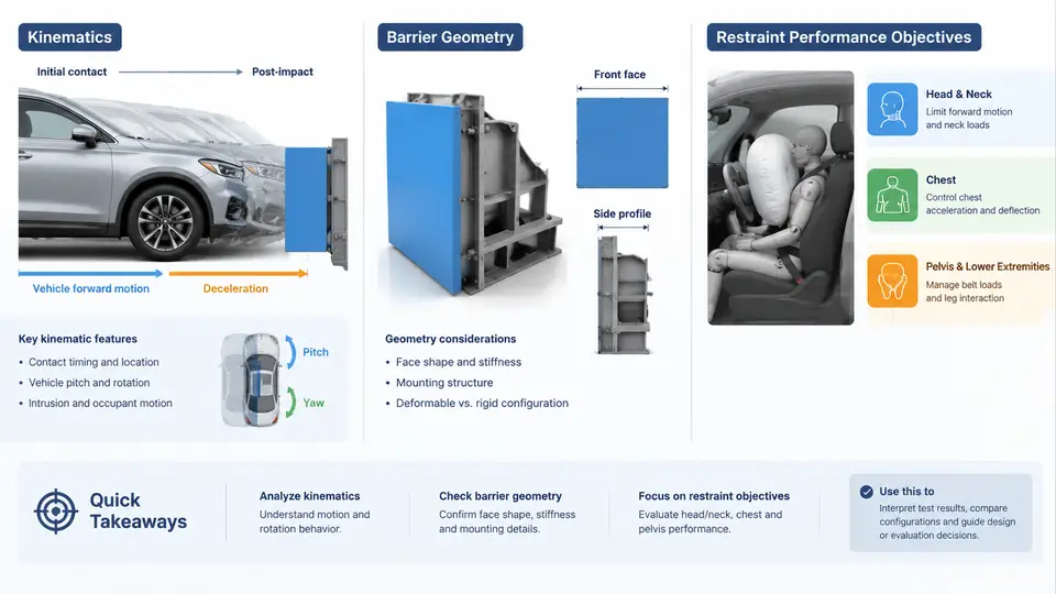
Small-overlap frontal crashes occupy a distinct corner of occupant safety engineering. Unlike the full-frontal and 40% offset tests that dominated regulation for decades, a small-overlap impact concentrates the collision force into a narrow strip of the vehicle's front structure, often only 25% of the vehicle width or less. The Insurance Institute for Highway Safety (IIHS) formalized this as the small overlap front test, driving a 40 mph (64 km/h) moving deformable barrier into a rigid 5 ft (1.5 m) tall barrier with a 25% overlap on the driver side. The result is a loading path that largely bypasses the longitudinal rails, forcing engineers to rethink both structural design and restraint strategy.
Kinematics of the Small-Overlap Event
In a full-frontal crash, the two longitudinal rails share the load symmetrically, and the occupant compartment decelerates along the vehicle's longitudinal axis. In a small-overlap event, the barrier contacts the outboard edge of the front structure — typically the bumper corner, headlamp area, and the outboard portion of the rail or a dedicated "shotgun" structure. Because the primary energy-absorbing members are not engaged symmetrically, the vehicle experiences a strong yaw moment and lateral displacement. The occupant compartment rotates and translates laterally away from the barrier, while the occupant continues forward and outward due to inertia.
This produces two coupled kinematic effects that define the restraint problem:
- Lateral excursion of the occupant: The occupant's torso and head move outboard relative to the vehicle interior, increasing the risk of contact with the A-pillar, door, or side window.
- Asymmetric deceleration: The vehicle's center of gravity decelerates less uniformly than in a symmetric crash, and the occupant restraint loads become uneven between the inboard and outboard sides.
The occupant's motion is best understood in the vehicle reference frame. Define the vehicle's longitudinal axis as x (positive forward), lateral axis as y (positive toward the driver's left, i.e., outboard for a left-hand-drive vehicle), and vertical axis as z (positive upward). In a driver-side small-overlap crash, the occupant's head and torso acquire a positive y velocity relative to the vehicle, driving them toward the A-pillar and side glass. This is the opposite of the symmetric frontal case, where the dominant relative motion is along x.
Barrier Geometry and Its Consequences
The IIHS small-overlap barrier is a rigid, non-deformable structure with a 25% overlap. Its height — approximately 5 ft — is deliberately chosen to sit above the bumper beam and below the hood line, engaging the upper rail, shock tower, and hinge pillar region rather than the lower load path. This geometry means the vehicle cannot rely on the bumper beam or lower rail to absorb energy; instead, the load must be redirected through the upper structure and, ideally, into the occupant compartment's safety cage.
Key geometric parameters that influence the outcome include:
| Parameter | Typical Value / Range | Effect on Crash Response |
|---|---|---|
| Overlap ratio | 25% (IIHS), 15–30% in real-world | Lower overlap increases yaw and lateral excursion |
| Barrier height | ~1.5 m (5 ft) | Engages upper rail and hinge pillar, bypasses bumper |
| Impact speed | 40 mph (64 km/h) | Sets the kinetic energy budget for restraint design |
| Vehicle mass | 1,500–2,500 kg | Scales the total energy and required restraint capacity |
Because the barrier is rigid, the vehicle must absorb essentially all of the crash energy through its own deformation. The outboard front structure — upper rail, shock tower, apron, and hinge pillar — becomes the primary crush zone. If these members fail to manage the load, the wheel and suspension components can be pushed rearward into the footwell, and the A-pillar can be forced inward toward the occupant.
Restraint Performance Objectives
The restraint system in a small-overlap crash must accomplish three objectives that are more demanding than in a symmetric frontal impact:
- Manage occupant kinematics in both x and y: The seat belt and airbag must control forward motion while also limiting lateral excursion. This often requires a seat-mounted side airbag and a side curtain airbag with sufficient coverage and inflation pressure to cushion the head against the A-pillar and side glass.
- Prevent occupant contact with intruding structure: The restraint must keep the head and torso away from the A-pillar, door trim, and window frame, which may be displaced inward by the barrier. This is a packaging and timing problem: the airbag must deploy before the occupant reaches the intruding surface.
- Distribute loads to reduce injury metrics: Belt forces, airbag pressures, and seat structure must be tuned so that head injury criterion (HIC), chest deflection, and femur loads remain within acceptable limits. In small overlap, the outboard shoulder belt may slip off the shoulder, so belt geometry and pretensioning are critical.
Design implication: A restraint system optimized only for full-frontal crashes will typically underperform in small overlap. The lateral component of occupant motion demands additional countermeasures — side airbags, seat-mounted thorax bags, and sometimes a driver-side knee airbag — that are not exercised in symmetric tests.
Visualizing the Load Path and Occupant Motion
The following SVG illustrates the small-overlap configuration, the primary load path through the outboard structure, and the resulting occupant kinematics. It shows the barrier position, the engaged vehicle structures, and the lateral excursion of the occupant relative to the vehicle interior.
The diagram shows the barrier engaging only the outboard portion of the vehicle. The upper rail and A-pillar carry the primary load, while the occupant moves both forward (+x) and laterally (+y) toward the A-pillar. The side airbag is positioned to intercept the head and torso before they contact the intruding structure.
Practical Engineering Considerations
When designing or evaluating a restraint system for small overlap, engineers typically work with a combination of sled tests, component tests, and full-vehicle crash simulations. A useful starting point is to define the occupant excursion budget: the maximum allowable lateral and forward displacement of the head and chest before contact with intruding surfaces. This budget is derived from the vehicle's interior geometry and the expected structural deformation.
For example, if the A-pillar is expected to intrude 100 mm laterally at the occupant's head height, and the head is expected to move 150 mm laterally relative to the vehicle, the side airbag must span at least 250 mm of lateral space and deploy within the first 20–30 ms of the crash. These numbers are illustrative and must be validated through simulation and testing for each vehicle program.
Practical tip: In small-overlap restraint tuning, the outboard shoulder belt anchor and the seat-mounted side airbag are the two most influential parameters for controlling lateral head excursion. Moving the shoulder anchor outboard and upward can reduce belt slip, while increasing side airbag pressure and coverage can reduce head contact with the A-pillar.
Understanding the kinematics, barrier geometry, and restraint objectives of small-overlap crashes provides the foundation for the rest of this course. The next chapters will build on this by examining structural countermeasures, airbag deployment strategies, and the test and simulation methods used to validate performance.