1. Seatbelt anchorage systems overview
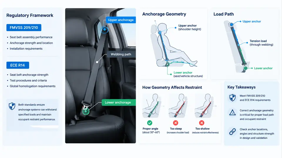
A seatbelt is only as effective as the structure it is bolted to. The belt webbing, retractor, buckle, and pretensioner form the visible restraint system, but the anchorage points — the reinforced locations on the body-in-white (BIW) where the belt loads are transferred into the vehicle structure — determine whether the restraint can actually develop its designed force. Anchorage geometry, meaning the three-dimensional positions of the upper, lower, and buckle anchorages relative to the occupant and to each other, governs belt routing, load distribution, and ultimately occupant kinematics in a crash. This chapter establishes the regulatory framework and explains why anchorage geometry is a first-order design variable rather than a packaging afterthought.
The Three Anchorage Points and the Restraint Load Path
A three-point belt system uses three anchorage locations. The D-ring (upper anchorage, often on the B-pillar or seat back) sets the shoulder belt's take-off point. The lower outboard anchorage (lap anchor) fixes the outboard end of the lap belt, and the buckle anchorage (inboard anchor) receives the buckle stalk. During a frontal impact, the occupant's torso loads the shoulder belt, which transfers force through the D-ring into the pillar and roof structure; the lap belt transfers force through the two lower anchors into the floor and rocker. The buckle anchor typically carries a smaller but non-trivial share and must resist both tension and bending from the stalk geometry.
The load path is therefore not a single chain but a branched network. A poorly placed D-ring can cause the shoulder belt to load the pillar in an off-axis direction, producing local bending and potential anchorage pull-out. A lap anchor positioned too far inboard allows the lap belt to ride up over the pelvis, increasing the risk of submarining. These are geometric failures, not material failures, which is why geometry must be treated as a controlled design parameter.
Regulatory Framework: FMVSS 209 and FMVSS 210
In the United States, two Federal Motor Vehicle Safety Standards govern seatbelt systems. FMVSS 209 (Seat Belt Assemblies) regulates the belt hardware itself — webbing strength, elongation, retractor performance, buckle release force, and hardware durability. FMVSS 210 (Seat Belt Assembly Anchorages) regulates the anchorage points in the vehicle structure. FMVSS 210 is the standard that directly constrains anchorage geometry and structural strength.
FMVSS 210 requires each anchorage to withstand a specified force applied through a test fixture that simulates the belt geometry. For passenger cars, the typical requirement is a 22,241 N (5,000 lbf) load applied to the anchorage assembly, with the force vector aligned to the belt's installed angle. The standard also defines the seating reference point (S-point) and the torso reference line, which are used to locate the anchorage zones. Anchorage positions must fall within specified zones relative to the S-point; for example, the upper anchorage must lie within a defined region above and behind the shoulder reference point. These zones exist because the standard assumes a nominal occupant posture, and geometry outside the zones may not restrain that posture correctly.
A critical detail: FMVSS 210 tests the anchorage as a system, not just the bolt. The test fixture applies load through a representative belt path, so the direction of the force depends on where the anchorage sits. Moving an anchor by 20 mm can change the load vector by several degrees, which changes the stress state in the surrounding sheet metal. This is the regulatory reason geometry matters: compliance is evaluated at the installed position, not at an idealized one.
ECE R14 and the European Approach
In Europe, UN ECE Regulation No. 14 (ECE R14) governs safety-belt anchorages. ECE R14 is broadly similar in intent to FMVSS 210 but differs in test methodology and force levels. ECE R14 specifies a 13,500 N load for the anchorage test on passenger vehicles, applied through a test device that represents the belt geometry. The regulation also defines anchorage location zones relative to the H-point and the seat back angle, and it requires that anchorages be located so the belt does not contact the occupant's neck or slip off the shoulder.
The practical difference for designers is that ECE R14 and FMVSS 210 use different reference points (H-point versus S-point), different force magnitudes, and slightly different zone definitions. A vehicle sold in both markets must satisfy both. This often forces the anchorage geometry into the intersection of the two zone sets, which can be more restrictive than either alone. The table below summarizes the key comparison.
| Parameter | FMVSS 210 | ECE R14 |
|---|---|---|
| Scope | Anchorage strength and location | Anchorage strength and location |
| Reference point | S-point (seating reference point) | H-point (hip point) |
| Typical test load (passenger car) | 22,241 N (5,000 lbf) | 13,500 N |
| Load application | Through belt-path fixture | Through belt-path fixture |
| Zone definition | Zones relative to S-point and torso line | Zones relative to H-point and seat back angle |
| Key geometric concern | Anchorage within specified zones | Belt must not contact neck or slip off shoulder |
Why Anchorage Geometry Drives Occupant Restraint
Geometry affects restraint performance through three mechanisms: belt routing, load vector, and occupant kinematics.
Belt routing. The D-ring position determines the shoulder belt angle across the torso. If the D-ring is too low or too far forward, the belt may cross the neck or slide off the shoulder during a crash. If it is too high, the belt may not engage the pelvis correctly. The lap anchor position determines whether the lap belt sits on the pelvic bone or rides up into the abdomen. Both are geometric outcomes.
Load vector. The angle at which the belt approaches each anchorage sets the direction of the force applied to the BIW. A D-ring mounted on a vertical pillar face receives load primarily in shear; one mounted on a horizontal surface receives load in tension. The surrounding sheet metal must be designed for that specific vector. Changing the anchor position changes the vector, which can turn an adequate structure into an inadequate one without any change in material or thickness.
Occupant kinematics. The relative positions of the three anchors define the belt's effective geometry, which in turn controls how the occupant moves in a crash. A wider lap anchor spacing produces a more stable pelvis restraint. A higher D-ring produces more torso rotation control. These are not abstract preferences; they are measurable differences in occupant excursion and injury criteria.
Design principle: Treat the three anchorage points as a single geometric system. Optimizing one anchor in isolation can degrade the belt path and the load distribution across the other two. The objective is a belt geometry that keeps the lap belt on the pelvis, the shoulder belt on the clavicle, and the load vectors within the structural capacity of the BIW.
Anchorage Geometry in Practice: A Worked Example
Consider a mid-size sedan with a seat H-point at (x = 1,250 mm, z = 320 mm) in vehicle coordinates, where x is longitudinal (positive forward) and z is vertical (positive up). The shoulder reference point is approximately 500 mm above the H-point along the torso line, giving a shoulder point near (x = 1,180 mm, z = 820 mm).
Suppose the initial D-ring position is at (x = 1,050 mm, z = 950 mm). The shoulder belt vector from the shoulder point to the D-ring is:
dx = 1,050 - 1,180 = -130 mm
dz = 950 - 820 = +130 mm
angle from vertical = atan(130 / 130) = 45 degrees
A 45-degree shoulder belt angle is steep and may cause the belt to load the pillar in an off-axis direction. If the D-ring is moved to (x = 1,020 mm, z = 1,000 mm), the vector becomes:
dx = 1,020 - 1,180 = -160 mm
dz = 1,000 - 820 = +180 mm
angle from vertical = atan(160 / 180) = 41.6 degrees
The change is modest, but the load vector at the anchorage shifts by several degrees, and the belt path across the shoulder changes. In a real program, this would be evaluated with a belt-fit check and a structural CAE model to confirm the anchorage zone remains within FMVSS 210 and ECE R14 limits. The point is that small geometric changes have measurable structural and restraint consequences.
Practical check: Before committing to an anchorage position, verify three things: (1) the belt path clears the occupant's neck and shoulder, (2) the anchorage lies within the regulatory zone for both target markets, and (3) the load vector at the anchorage is compatible with the local BIW structure. These checks are faster and cheaper than a full sled test.
Visualizing the Anchorage System and Load Path
The diagram below shows the three anchorage points, the belt path, and the primary load paths into the vehicle structure. It also indicates the regulatory reference points (S-point/H-point and shoulder reference) that define the anchorage zones.
Key Takeaways for Anchorage Design
- Regulatory compliance is geometric. FMVSS 210 and ECE R14 define anchorage zones relative to reference points; a position that satisfies one market may not satisfy the other.
- Geometry sets the load vector. The anchorage position determines the direction and magnitude of force transferred into the BIW, which in turn determines the structural reinforcement required.
- The three anchors form a system. D-ring, lap anchor, and buckle anchor must be optimized together to achieve correct belt routing and occupant kinematics.
- Small changes have measurable effects. A 20–50 mm shift in anchorage position can change belt angle, load vector, and regulatory zone compliance, so geometry must be controlled and verified early in the design process.
With the regulatory framework and the geometric principles established, the next step is to examine how anchorage positions are defined in vehicle coordinates and how belt-fit and structural analyses are used to converge on a compliant, effective design.