1. Restraint system overview
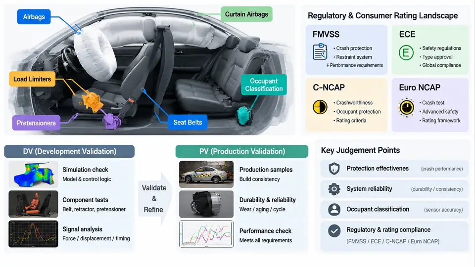
An occupant restraint system is not a single device but a coordinated chain of pyrotechnic, mechanical, and electronic subsystems that must deploy within milliseconds of a crash event. Before any discussion of validation planning, it is essential to establish what each subsystem does, how the regulatory and consumer-rating landscape shapes design targets, and where Design Verification (DV) and Production Validation (PV) sit within the product development lifecycle.
Core Restraint Subsystems
Seat belts remain the primary restraint. A three-point belt consists of a lap and shoulder webbing routed through a retractor, a buckle, and anchor points. The retractor contains an emergency locking mechanism (ELR) that locks webbing payout under vehicle deceleration or belt acceleration thresholds, typically triggered by a vehicle-sensitive inertia mass and a webbing-sensitive mechanism. Belt geometry — anchor positions, D-ring height, and webbing routing — determines how occupant load is distributed across the pelvis and thorax.
Pretensioners remove belt slack at the onset of a crash. Pyrotechnic pretensioners use a small gas generator to drive a piston or ball chain that retracts the buckle or spool, pulling the occupant into the seat before the belt force peaks. They are characterized by pull-in distance (commonly 60–120 mm at the buckle or retractor) and actuation time (typically 10–20 ms after trigger). Pretensioners are often paired with load limiters, which cap the maximum belt force transmitted to the occupant. A torsion bar inside the retractor, or a tearing stitch in the webbing, allows controlled webbing payout once a force threshold (for example, 4–6 kN at the shoulder) is exceeded, reducing chest deflection and rib fracture risk.
Airbags supplement the belt by distributing impact forces over a larger area. Frontal driver and passenger airbags, side thorax airbags, side curtain airbags, and knee airbags each have distinct deployment envelopes. Key parameters include inflator output (gas mass and pressure curve), vent sizing, cushion volume, and tether geometry. The airbag control unit (ACU) uses accelerometers and pressure sensors to classify the crash severity and decide deployment timing, typically within 10–40 ms for a frontal event.
Occupant classification systems (OCS) determine whether a passenger seat is occupied, and if so, by what — an adult, a child seat, or a rear-facing infant seat. Pressure-sensitive mats, capacitive sensors, or camera-based systems feed the ACU, which may suppress the passenger airbag or switch it to a low-risk deployment mode. This is a regulatory requirement under FMVSS 208 for the passenger seat.
Regulatory and Consumer Rating Landscape
Restraint performance is governed by two overlapping frameworks: government regulation and consumer rating programs. FMVSS (Federal Motor Vehicle Safety Standards) in the United States sets mandatory minimum requirements. FMVSS 208 governs occupant crash protection, including frontal airbag deployment and unbelted test requirements. FMVSS 209 covers seat belt assemblies, and FMVSS 213 addresses child restraint systems. ECE regulations in Europe — ECE R16 (seat belts), R94 (frontal impact), and R95 (lateral impact) — define type-approval tests that vehicles must pass before sale.
Consumer rating programs push beyond regulatory minima. C-NCAP (China New Car Assessment Program) and Euro NCAP use higher impact speeds, additional crash modes (such as pole side impact and far-side occupant protection), and scoring systems that reward advanced restraint features like adaptive load limiters and multi-stage airbags. A vehicle that merely passes FMVSS 208 may score poorly in Euro NCAP if its restraint system does not manage occupant kinematics across a wider range of crash severities and occupant sizes.
The practical consequence is that restraint system requirements are typically written to satisfy the most demanding applicable rating program, not just the regulation. For example, a Euro NCAP frontal offset test at 64 km/h with a 40% overlap produces a different deceleration pulse and occupant loading than the FMVSS 208 full-frontal rigid barrier test at 56 km/h. The restraint calibration — pretensioner timing, load limiter force level, airbag vent size — must be tuned to perform well in both.
DV and PV: Definitions and Lifecycle Role
Design Verification (DV) confirms that the design intent meets the specified requirements. DV testing is performed on prototype or pre-production parts that represent the intended design, but not necessarily the final production process. The goal is to answer: "Does this design work?" DV typically includes component-level tests (belt retractor locking, pretensioner output, airbag inflator pressure curve), subsystem tests (seat-integrated restraint performance), and sled tests that simulate full-vehicle deceleration pulses. Boundary conditions — extreme temperatures, aged parts, worst-case occupant positions — are deliberately included to expose design weaknesses early.
Production Validation (PV) confirms that parts manufactured with production tooling, processes, and operators consistently meet the same requirements. PV answers: "Can we build this design correctly, every time?" PV samples must come from the actual production line, not a pilot line. The test matrix mirrors DV but focuses on process capability: statistical measures such as Cpk or Ppk on critical-to-function parameters (for example, pretensioner pull-in distance or airbag inflator gas output) are evaluated alongside pass/fail crash tests. A PV failure indicates a manufacturing or process issue, not a design flaw — though in practice, the boundary between the two can blur when a design is marginal.
Key distinction: DV proves the design is correct. PV proves the process can reproduce it. Both are required before production release. A common mistake is to treat DV as a one-time event; in reality, any design change after DV — even a material substitution — triggers a re-evaluation and potentially a partial or full re-test.
How the Pieces Fit Together
The validation sequence follows the product development timeline. During concept and design phases, DV planning defines the test matrix based on regulatory and rating requirements. As prototypes become available, DV testing executes. Findings feed back into design iterations. Once the design is frozen and production tooling is ready, PV testing begins. Successful PV, combined with a Production Part Approval Process (PPAP) submission and a Part Submission Warrant (PSW), supports the production release decision.
For restraint systems specifically, the critical path often runs through full-vehicle crash tests, which are expensive and schedule-constrained. A typical program might require 20–40 full-vehicle crash tests across DV and PV, plus hundreds of sled and component tests. Understanding which tests are regulatory (mandatory pass/fail), which are rating-driven (score optimization), and which are internal engineering checks (robustness) is essential for allocating budget and schedule.
Practical note: When reviewing a DV/PV plan, always verify that the test matrix explicitly maps each test to a requirement source — FMVSS section, ECE regulation paragraph, or Euro NCAP protocol version. A test without a traceable requirement is either redundant or, worse, masking a gap.
With this foundation — the subsystems, the regulatory and rating context, and the DV/PV framework — subsequent chapters can address specific validation methods, test setups, data analysis, and release criteria in detail.