1. Restraint robustness engineering across
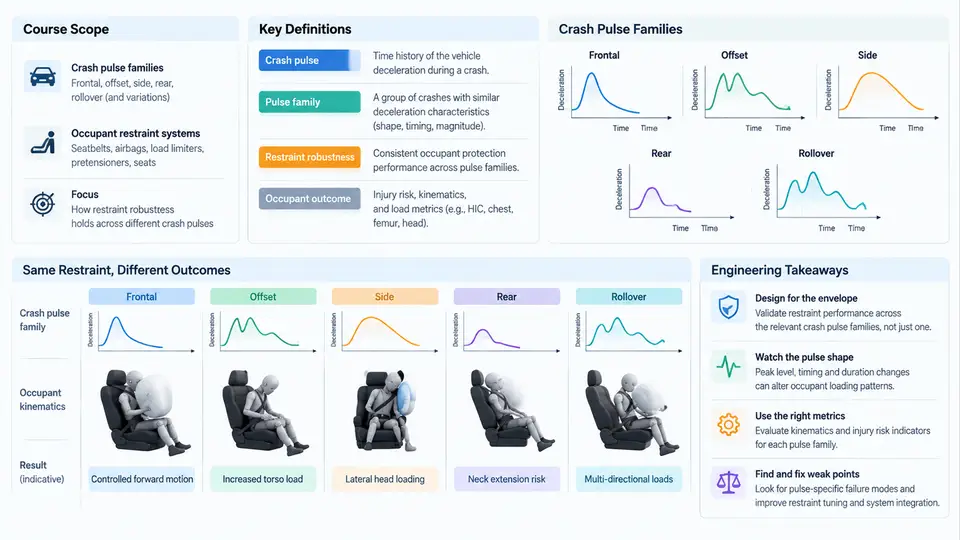
Crashworthiness engineers rarely get to choose the crash pulse. A restraint system that performs beautifully in a 56 km/h full-frontal rigid barrier test may deliver marginal or even failing occupant outcomes in a 64 km/h offset deformable barrier (ODB) impact, a 32 km/h pole side impact, or a low-speed rear-end event. The pulse — the acceleration–time history imposed on the vehicle body at the restraint anchorages — is not a single design target but a family of loading conditions. Restraint robustness engineering is the discipline of designing occupant protection systems that remain effective across that family, rather than being tuned to a single certification pulse.
1.1 What "Pulse Family" Means in Practice
A crash pulse is characterized by its shape (typically a filtered acceleration–time curve), peak acceleration, duration, and the resulting velocity change (Δv). Different test and real-world configurations produce distinctly different pulses:
| Configuration | Typical Δv | Pulse character | Dominant restraint challenge |
|---|---|---|---|
| Full-frontal rigid barrier, 56 km/h | ~56 km/h | High peak, short duration, steep rise | Early belt loading, high chest g |
| Offset deformable barrier (ODB), 64 km/h | ~64 km/h | Lower peak, longer duration, asymmetric | Yaw/rotation, belt slip, airbag timing |
| Side pole, 32 km/h | ~32 km/h | Very short, high local intrusion | Limited crush space, thorax/pelvis loading |
| Rear impact, 80 km/h | ~80 km/h | Moderate peak, long duration | Head/neck kinematics, seatback stiffness |
| Low-speed bumper, 16 km/h | ~16 km/h | Low peak, very short | No restraint deployment; injury avoidance |
These are not interchangeable. A restraint calibration that minimizes chest deflection in the full-frontal pulse may allow excessive forward excursion in the ODB pulse because the belt force limiter (load limiter) releases too early relative to the longer deceleration phase. Conversely, a stiff load limiter that controls excursion in ODB may produce excessive chest acceleration in the short, high-peak frontal pulse.
1.2 Key Definitions
- Crash pulse: The acceleration–time history measured at a structural reference point (e.g., B-pillar base or tunnel) during a crash event, typically filtered per SAE J211/1 (Channel Filter Class 60 or 180).
- Δv (delta-v): The integral of the crash pulse over the event duration; the velocity change experienced by the vehicle structure.
- Restraint robustness: The ability of the occupant restraint system (belts, pretensioners, load limiters, airbags, seat structure) to maintain occupant injury metrics below thresholds across the full range of pulses within the design envelope.
- Pulse-dependent occupant outcome: The phenomenon where the same restraint hardware produces significantly different injury metrics (HIC, chest deflection, Nij, etc.) when subjected to different pulses.
- Coupling: The interaction between vehicle deceleration (pulse) and occupant deceleration (restraint force), governed by the relative motion between occupant and vehicle interior.
1.3 The Engineering Problem: Why Pulse Dependence Matters
The core engineering problem is that restraint systems are tuned to specific pulses during development, but must perform across a family of pulses in the field. This mismatch creates three distinct failure modes:
- Over-tuning to a single pulse: A load limiter set to 4 kN may be optimal for a 56 km/h frontal pulse but insufficient to control excursion in a 64 km/h ODB pulse, where the occupant has more time to travel forward.
- Deployment timing sensitivity: Airbag deployment timing is often calibrated to a specific pulse rise rate. In a slower-rising pulse, the airbag may deploy too early (out of position) or too late (bottoming out).
- Occupant size and posture variation: The same pulse produces different outcomes for a 5th percentile female versus a 95th percentile male, because the restraint coupling depends on occupant mass, stiffness, and seating position.
Example — pulse-dependent chest deflection: Consider a restraint system with a 3.5 kN load limiter and a pretensioner firing at 15 ms. In a 56 km/h full-frontal pulse (peak ~40 g, duration ~80 ms), chest deflection might measure 32 mm. In a 64 km/h ODB pulse (peak ~28 g, duration ~120 ms), the same system may produce 42 mm chest deflection because the longer deceleration phase allows more belt payout and occupant excursion. Both are "the same hardware," but the outcome differs by 30%.
1.4 Visualizing the Pulse–Restraint–Outcome Chain
The following diagram shows how a pulse family propagates through the restraint system to produce occupant outcomes. The key insight is that the pulse is not a single input but a set of inputs, and the restraint system must be robust across that set.
1.5 Course Scope and Engineering Approach
This course addresses the full engineering workflow for restraint robustness across pulse families. The scope includes:
- Pulse characterization and classification: How to measure, filter, and parameterize crash pulses; how to define a pulse family for a given vehicle program.
- Restraint system modeling: Lumped-parameter and finite element models of belt, pretensioner, load limiter, airbag, and seat; how to calibrate them against sled and vehicle tests.
- Robustness metrics: How to quantify pulse sensitivity — sensitivity coefficients, response surfaces, and worst-case analysis.
- Design optimization: How to select restraint parameters (load limiter force, pretensioner timing, airbag vent size) that minimize worst-case injury metrics across the pulse family.
- Validation and verification: How to design a test matrix that covers the pulse family without exhaustive testing; how to use CAE to interpolate between test points.
Practical note: In real programs, the pulse family is not infinite. It is typically defined by a small set of regulatory and consumer-test pulses (e.g., FMVSS 208, Euro NCAP, C-NCAP) plus a set of "off-nominal" pulses derived from field data or vehicle-to-vehicle compatibility studies. The engineering task is to ensure robustness across this finite but diverse set.
1.6 A Worked Example: Sensitivity of Chest Deflection to Pulse Duration
To make the problem concrete, consider a simplified lumped-parameter model of the occupant–restraint system:
m_occ * x_occ'' = -F_belt(x_occ - x_veh) - F_airbag(x_occ - x_veh)
m_veh * x_veh'' = -F_pulse(t) + F_belt + F_airbag
where m_occ is occupant mass, m_veh is vehicle mass, F_belt is belt force (a function of relative displacement, with load limiter plateau), and F_pulse(t) is the crash pulse force. For a given pulse, the chest deflection is approximately the maximum relative displacement |x_occ - x_veh|.
If we run this model with a 3.5 kN load limiter and two pulses — a short 80 ms pulse and a long 120 ms pulse with the same Δv — the long pulse produces roughly 25–35% more chest deflection because the belt force plateau is sustained for a longer time, allowing more occupant travel. This is the essence of pulse-dependent outcome: the same hardware, different pulse, different result.
Common pitfall: Engineers often calibrate restraint systems to a single "worst-case" pulse. But the worst case for chest deflection may not be the worst case for head injury or submarining. Robustness engineering requires evaluating the full pulse family against all relevant injury criteria simultaneously.
1.7 Key Takeaways for This Chapter
- Crash pulses form a family, not a single design point. Restraint robustness means performing well across that family.
- Pulse-dependent occupant outcomes arise from the interaction between pulse shape (peak, duration, Δv) and restraint characteristics (force limit, timing, stiffness).
- The engineering problem is to minimize the variance of injury metrics across the pulse family, not just to optimize for one pulse.
- This course will cover pulse characterization, restraint modeling, robustness metrics, optimization, and validation — all aimed at closing the robustness gap.
In the chapters that follow, we will build the tools to quantify and reduce pulse sensitivity, starting with how to measure and classify crash pulses in a way that supports robust restraint design.