1. Restraint system architecture and crash
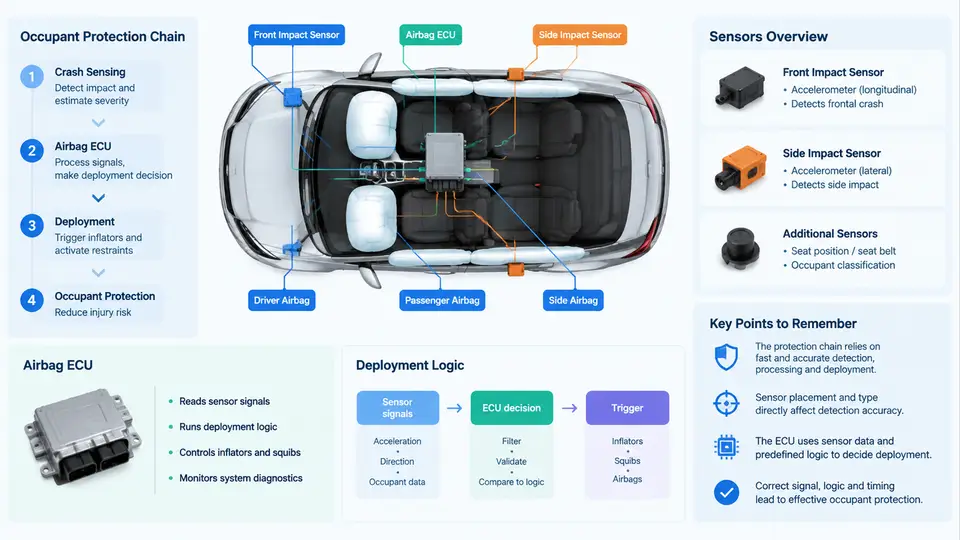
An occupant protection system is not a single device but a coordinated chain of sensing, decision-making, and energy-absorbing elements that must all function within a few tens of milliseconds. Understanding this chain — and the role each component plays — is the foundation for every algorithm you will develop later in this course. This chapter establishes the architectural vocabulary and the physical principles that govern crash detection.
The Occupant Protection Chain
The protection chain describes the sequence from impact to occupant restraint. It begins with the crash event itself: kinetic energy is transferred into the vehicle structure, producing deformation and a characteristic deceleration pulse. The sensing subsystem — accelerometers, pressure sensors, and satellite sensors — converts this physical event into electrical signals. The airbag ECU (Electronic Control Unit) processes those signals, applies deployment logic, and decides whether and when to fire each restraint. Finally, the actuation stage triggers inflators, seat-belt pretensioners, and related devices.
Each link introduces latency. A typical frontal accelerometer has a signal chain delay of 1–3 ms; the ECU's analog-to-digital conversion and filtering add another 1–2 ms; the deployment decision and squib firing add roughly 2–5 ms. The total loop from impact to airbag full inflation is typically 30–50 ms for a frontal airbag. This timing budget is the single most important constraint in restraint algorithm design.
Airbag ECU Architecture
The airbag ECU is the central processing node. Internally it contains:
- Analog front-end: signal conditioning, anti-aliasing filters, and ADCs for each sensor channel.
- Microcontroller: runs the crash discrimination algorithm, manages sensor fusion, and executes safety checks.
- Safety logic: independent watchdog and arming circuits that prevent unintended deployment.
- Squib drivers: high-side/low-side switches that deliver firing current to each initiator.
- Backup power: a capacitor that maintains operation if the vehicle battery is disconnected during impact.
In a typical configuration, the ECU is mounted on the vehicle tunnel or under the center console, where it is mechanically coupled to the body structure. This mounting position determines the accelerometer's measurement axis and must be accounted for in algorithm calibration.
Sensor Types and Their Roles
Modern restraint systems use a combination of sensor types:
| Sensor | Location | Primary Function |
|---|---|---|
| Frontal accelerometer | ECU or front crash zone | Measures longitudinal deceleration for frontal deployment |
| Side pressure sensor | Inside door cavity | Detects pressure rise from side impact |
| Side accelerometer | B-pillar or sill | Confirms side impact and discriminates severity |
| Rollover sensor | ECU or roof | Measures angular rate and lateral acceleration |
| Seat occupancy sensor | Seat cushion | Suppresses passenger airbag when seat is empty |
Each sensor has a defined measurement range, sensitivity, and frequency response. For example, a frontal accelerometer might have a range of ±50 g to ±250 g with a bandwidth of 0–400 Hz. The pressure sensor in a side door typically responds to pressure changes of 0–500 kPa within 5–10 ms. These specifications directly influence the algorithm's ability to distinguish a crash from a rough road event.
Deployment Logic Overview
Deployment logic is the decision layer that converts sensor data into a fire/no-fire command. It must solve two problems simultaneously: discrimination (is this a crash?) and severity estimation (how severe is it?).
A common approach uses a velocity-based algorithm. The ECU integrates the filtered acceleration signal to obtain a velocity change, Δv. When Δv exceeds a calibrated threshold within a defined time window, deployment is triggered. The threshold is not a single value but a curve — often called a deployment map — that varies with time and vehicle speed. Lower thresholds apply at higher vehicle speeds because the required protection level is greater.
More advanced systems use energy-based or frequency-domain methods. Crash pulses contain significant energy in the 10–100 Hz range, while rough-road inputs tend to be lower in amplitude and different in spectral content. By computing a short-time Fourier transform or a band-pass energy metric, the algorithm can improve discrimination without increasing latency.
Signal Flow and Decision Path
The following diagram shows the signal flow from impact through the sensing and decision stages to deployment. It highlights the parallel paths for frontal and side events and the role of the safety logic in gating the final firing command.
From Architecture to Algorithm
With the architecture established, the algorithm developer's task becomes concrete. You must know which sensor channels are available, their sample rates and noise characteristics, the ECU's computational budget, and the timing constraints imposed by the protection chain. A frontal algorithm running at 1 kHz sample rate has 1 ms per cycle to filter, integrate, compare against thresholds, and update state. A side algorithm may run at 2 kHz because side impacts develop faster.
The deployment logic itself is typically structured as a state machine: idle, crash detected, deployment confirmed, and post-deployment. Transitions depend on cumulative velocity change, energy metrics, and plausibility checks. The safety logic operates in parallel, ensuring that a single sensor fault or a software error cannot cause an unintended deployment.
In the next chapters, you will implement these concepts: filtering raw acceleration, computing Δv, calibrating thresholds, and validating against crash pulses. The architecture described here is the map; the algorithm is the territory you will learn to navigate.