1. Occupant classification and smart restra
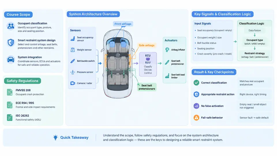
Modern frontal airbags were originally deployed with a single, fixed inflation energy tuned for an unbelted 50th-percentile male dummy. That assumption is no longer acceptable. A 45 kg fifth-percentile female driver sitting close to the steering wheel and an 85 kg 95th-percentile male occupant require fundamentally different restraint energies, and a rear-facing child seat must not receive a full-power frontal airbag deployment at all. Occupant classification (OC) exists to resolve this ambiguity: it measures who or what occupies a seat, and the smart restraint system converts that classification into a seat-specific, crash-severity-specific deployment decision.
This course covers the complete engineering chain from sensing to actuation. Over 30 chapters we move through sensor physics, seat-weight and pressure sensing, capacitive and time-of-flight occupant detection, image-based classification, crash severity estimation, restraint control algorithms, squib and dual-stage inflator driving, diagnostics and fault tolerance, regulatory validation, and production release. This first chapter establishes the vocabulary, the regulatory boundary conditions, and the reference architecture that every later chapter refines.
What the system must decide
A production occupant classification and smart restraint system answers four questions within the crash timeline, typically 10–40 ms from impact detection to squib firing decision:
- Is the seat occupied? An empty seat must not fire its airbag, which reduces repair cost and eliminates unnecessary deployment injury risk.
- By whom or by what? Categories include adult (large/small), child in a child restraint system (CRS), child directly on the seat, and objects such as bags or groceries.
- Where is the occupant? Seat position (fore/aft track), seat back angle, and occupant proximity to the instrument panel determine out-of-position (OOP) risk.
- How severe is the crash? Central acceleration, crash pulse shape, and belt-load information set the required restraint energy level.
The output is not a single boolean. It is a set of per-seat actuator commands: airbag suppression, low-power or high-power stage selection, adaptive belt load limiter threshold, and pretensioner firing. A typical mid-range vehicle today manages 6–10 squibs across driver, passenger, side, and curtain restraints.
Regulatory and rating framework
Two regulatory families dominate design requirements. In the United States, FMVSS 208 (49 CFR 571.208) mandates occupant protection and explicitly requires an occupant classification system capable of suppressing the frontal passenger airbag for a rear-facing CRS and for small children, with telltale indication to the driver. FMVSS 208 also defines the unbelted and belted test matrix, the 5th-percentile female and 95th-percentile male test dummies, and the OOP static deployment tests (the "12 OOP" positions) that constrain deployment energy.
In Europe and markets adopting UN regulations, UN R94 (frontal impact) and UN R137 (belted frontal, advanced restraint systems) define crash test performance, while UN R16 governs safety-belt and restraint-system installation. The Advanced Offset Frontal Impact (AOF) and Mobile Progressive Deformable Barrier (MPDB) tests in Euro NCAP add rating pressure toward adaptive restraint behaviour. Key regulatory constraints that shape architecture include:
| Requirement | Typical design consequence |
|---|---|
| Suppress airbag for rear-facing CRS (FMVSS 208 S19, S21) | Passenger seat must carry a dedicated OC sensor with CRS discrimination, plus a visible "PASSENGER AIRBAG OFF" telltale |
| OOP static deployment limits (FMVSS 208 S22–S24) | Dual-stage or multi-stage inflators with variable timing; suppression or low-power firing for near-panel occupants |
| Diagnostic and fault indication (FMVSS 208 S19.3, UN R16 Annex 8) | Continuous self-test, fault memory, and a telltale that must illuminate on any OC fault |
| EMC and environmental robustness (ISO 11452, ISO 16750) | Shielded sensor harness, differential signalling, temperature and humidity compensation in the OC ECU |
Note that regulations set the floor, not the target. A system that only satisfies FMVSS 208 suppression will still score poorly in consumer ratings and will not deliver the field performance expected of a modern vehicle. Design targets are therefore usually written against both the regulatory minimum and the internal rating target.
Reference system architecture
The architecture separates three functional domains: sensing, decision, and actuation. Keeping these domains distinct is what allows a single restraint control module (RCM) to serve multiple seat configurations and markets without redesigning the crash algorithm for every variant.
The sensing layer includes the occupant classification sensor (a pressure/bladder mat, a capacitive field sensor, or a combination), seat track position switches, seat belt buckle switches, belt tension or buckle load sensors, and the RCM's own accelerometers and safing sensor. The decision layer is the RCM, which hosts the crash discrimination algorithm, the occupant classification algorithm, and the deployment logic. The actuation layer comprises the squib drivers, the inflator stages, the pretensioners, and the adaptive load limiter. A dedicated OC ECU is sometimes used when the classification algorithm is too computationally heavy for the RCM, communicating over CAN or a dedicated sensor bus.
The dashed feedback path is important: squib loop continuity is measured continuously, and any open or shorted loop must be reported to the driver and stored in fault memory. This is a regulatory requirement, not a convenience feature.
From classification to deployment: a worked example
Consider a passenger seat in a mid-size sedan. The OC mat reports a cushion load of 28 kg distributed over the rear two-thirds of the seat, the seat track switch indicates the seat is in the rearmost position, the buckle switch is closed, and the capacitive sensor reports a large conductive body with low proximity to the instrument panel. The classification algorithm combines these into an "adult, belted, rear position" class.
Now suppose the RCM accelerometer records a 30 g peak, 60 ms duration frontal pulse. The severity estimator integrates the pulse and computes a Δv of approximately 45 km/h. The deployment logic looks up the restraint table for the class "adult, belted, rear position" at severity level 3 and issues: stage 1 fire at T+18 ms, stage 2 fire at T+45 ms, pretensioner fire at T+12 ms, load limiter set to high threshold. If the same crash occurred with the seat in the forward-most position and the occupant classified as a small female, the table would instead select stage 1 only, with the pretensioner fired earlier and the load limiter set to a lower threshold.
This table-driven structure is deliberate. It separates the classification problem from the deployment problem, so that a change in inflator output or a new market requirement modifies the table rather than the algorithm. The table itself is calibrated through sled testing and validated against the regulatory matrix.
Failure behaviour and safe states
Every sensing element can fail. A shorted OC mat, a disconnected buckle switch, or a corrupted CAN frame must not produce an unsafe deployment. The standard approach is a fail-safe default: if the occupant classification is unavailable or inconsistent, the passenger frontal airbag is suppressed and the telltale illuminates, while the driver frontal airbag remains fully functional because the driver seat is assumed occupied. This asymmetry reflects the regulatory priority: protecting the driver is mandatory, while suppressing an airbag in front of a possibly empty or child-occupied seat is the conservative choice.
Fault handling must also be deterministic in time. A fault detected 5 ms before the firing decision cannot be resolved by a full re-classification; the system must already have a valid class or a defined default. This is why OC algorithms run continuously at 100–200 Hz and publish a class with a validity flag, rather than computing on demand at crash time.
What this course delivers
By the end of the course you will be able to specify an occupant classification sensor suite for a given seat and market, implement and tune a classification algorithm against regulatory test cases, design a deployment table that satisfies both FMVSS 208 and UN R94/R137, integrate the RCM with the vehicle harness and diagnostics, and plan the validation campaign from component-level EMC testing through full-vehicle crash tests. The remaining chapters build each of these capabilities in sequence, starting with the sensor physics that make classification possible.