1. Multi-stage belt systems overview
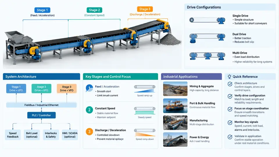
A multi-stage belt system is a material transport architecture in which two or more independently driven belt conveyors are arranged in series, in parallel, or in a hybrid topology to move bulk or unit loads across a long or geometrically complex route. The defining characteristic is not simply the number of belts, but the fact that each belt section has its own drive, its own speed reference, and its own control loop, while the overall material flow must remain coordinated. This distinction separates a true multi-stage system from a single long conveyor with multiple drive pulleys sharing one mechanical train.
Typical installations include mining overland conveyors, port bulk-handling terminals, cement and aggregate plants, biomass and waste-to-energy feed lines, and large distribution sorters. In each case, the route is broken into stages because of terrain, structural limits, transfer requirements, or the need to isolate sections for maintenance and fault containment.
Architecture and Stage Definition
A stage is a functional unit consisting of a belt, a drive station, a take-up system, and the associated instrumentation. Stages are connected by transfer chutes or transition conveyors. From a control perspective, each stage exposes a small set of signals to the plant control layer: run command, speed reference, actual speed, motor current or torque, belt slip or misalignment status, and fault status. The plant controller coordinates these signals across stages.
The most common architectures are:
- Series (cascade) architecture: material flows from Stage 1 to Stage 2 to Stage 3. Downstream stages must be ready before upstream stages start, and upstream stages must stop before downstream stages in a controlled sequence to avoid material spillage.
- Parallel architecture: multiple stages feed a common collection point or split from a common source. Coordination focuses on balancing flow and preventing overloading of the shared node.
- Hybrid architecture: combinations of series and parallel paths, often with diverter gates or reversible belts. Control logic must handle route selection and interlocking between branches.
Drive Configurations
The drive configuration determines how torque and speed are produced and how the belt is controlled. Common configurations in multi-stage systems include:
| Configuration | Typical Use | Control Implication |
|---|---|---|
| Single fixed-speed drive | Short transfer belts, constant feed | Simple start/stop; no speed matching |
| Variable frequency drive (VFD) | Most modern multi-stage systems | Speed reference per stage; soft start and speed matching |
| Dual or multiple drives per stage | High-capacity or long belts | Load sharing, torque balancing, master/slave control |
| Gearless permanent magnet drive | High-torque, low-speed applications | Direct torque control, reduced mechanical losses |
In a multi-stage system, the drive configuration of one stage affects the others. For example, if Stage 2 uses a VFD with a controlled ramp, Stage 1 must not push material faster than Stage 2 can accept. This is why speed matching and interlocking are central to multi-stage control strategy.
Industrial Applications and Operating Context
In mining, overland conveyors often consist of several stages with transfer towers. The control system must handle starting under load, controlled stopping to avoid material carry-back, and fault isolation so that a single stage fault does not cascade into a full-plant shutdown. In port terminals, multi-stage systems load and unload ships, where stage coordination directly affects throughput and ship turnaround time. In cement plants, raw material feed lines use multiple stages to blend and transport material to the kiln, where speed changes affect both energy consumption and process quality.
Each application imposes different constraints. Mining systems prioritize availability and fault tolerance. Port systems prioritize throughput and rapid mode changes. Process plants prioritize stable flow and integration with process control. These priorities shape the control strategy and the calibration requirements for each stage.
Control and Calibration Implications
Because each stage has its own drive and dynamics, the system cannot be treated as a single conveyor. Key implications include:
- Speed matching: adjacent stages must maintain a speed ratio that prevents material accumulation or starvation at the transfer point.
- Start/stop sequencing: downstream stages start first and stop last in a series architecture to keep the material path clear.
- Load sharing: multiple drives on one stage must share torque to avoid overload and belt stretch.
- Fault propagation: a fault in one stage must trigger a controlled response in adjacent stages, not an uncontrolled stop that causes spillage or belt damage.
- Calibration: each stage requires calibration of speed feedback, tension, belt slip detection, and drive torque limits. These calibrations must be consistent across stages for coordinated operation.
Visualizing the Architecture
The following diagram shows a three-stage series system with VFD-driven stages, a transfer point between each stage, and the signal flow between the plant controller and each stage drive. It also highlights the key coordination signals: speed reference, actual speed, and fault status.
Key Takeaways for Control Strategy
Understanding the architecture and drive configuration is the foundation for every later decision in this course. A multi-stage belt system is a coordinated network of independent drives, not a single machine. The control strategy must respect the physical coupling at transfer points, the dynamic differences between stages, and the operational priorities of the plant. Calibration is the process of aligning each stage's sensors, drives, and control loops so that the coordinated behavior is predictable and repeatable.
Before moving to detailed control design, verify the following for any multi-stage system:
- Each stage has a clearly defined speed reference source and feedback signal.
- Transfer points are identified as controlled interfaces with defined material flow constraints.
- Start/stop sequencing is documented for the chosen architecture (series, parallel, or hybrid).
- Drive configurations are known, including whether load sharing or torque balancing is required.
- Fault propagation paths are defined so that a single stage fault triggers a controlled response in adjacent stages.
These items form the baseline for the calibration and control work that follows. Without them, even a well-tuned individual drive can produce unstable or unsafe behavior when integrated into a multi-stage system.