1. Airbag deployment simulation landscape
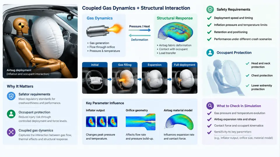
An airbag is a pyrotechnically driven pressure vessel that must inflate in tens of milliseconds, absorb a human body's kinetic energy, and then vent itself before the occupant rebounds into it. Every one of those functions is governed by gas dynamics: the rate at which propellant burns, the mass flow through the inflator nozzle, the pressure that builds inside the cushion, the flow through vent holes and fabric porosity, and the way all of this couples to the moving occupant. This chapter establishes why coupled gas-dynamics simulation has become the backbone of modern restraint system design, and what a credible deployment model must reproduce.
1.1 What the safety requirements actually demand
Restraint performance is judged against regulated and consumer-facing test protocols. In the United States, FMVSS 208 defines frontal barrier and offset deformable barrier tests with unbelted and belted dummies; FMVSS 226 covers ejection mitigation through side curtain airbags. In Europe, UNECE R94 and R95 set frontal and lateral crash requirements, while Euro NCAP and its counterparts in other regions add rating-based thresholds that are typically stricter than the legal minimum. The measurable outputs are familiar: head injury criterion (HIC), chest deflection and the 3 ms chest acceleration clip, neck injury criteria (Nij), femur loads, and for side impact, rib deflection and abdominal penetration.
What matters for simulation is that these criteria are not properties of the airbag alone. They emerge from the interaction of three subsystems: the occupant (mass, posture, belt usage), the restraint hardware (inflator, cushion geometry, vents, tethers, fold pattern), and the vehicle structure (deceleration pulse, intrusion, seat and steering column behavior). A cushion that is too aggressive produces high head acceleration; one that is too soft lets the head travel too far and strike the structure. The design window is narrow, and it is set by gas dynamics.
1.2 Why the gas phase cannot be treated as a lookup table
Early restraint CAE used a simplified approach: prescribe the cushion pressure as a function of time, or inflate the cushion with a uniform pressure boundary condition. That works when the cushion is small, the inflator is well characterized, and the occupant is far from the module. It fails in exactly the cases that dominate modern development:
- Out-of-position (OOP) occupants. When a child or a small-stature adult is close to the module at deployment, the cushion contacts the body while it is still inflating. The pressure history is then a function of the occupant's position, not a prescribed curve. A one-way pressure input cannot capture the resulting membrane contact loads.
- Dual-stage and adaptive inflators. These fire two charges with a controlled delay, and the split depends on crash severity, belt status, and occupant classification. The gas generation rate is a decision variable, so it must be computed, not assumed.
- Venting and porosity. Gas escapes through sew holes, vent holes, and the fabric weave itself. The vent mass flow depends on the instantaneous pressure difference across the fabric, which depends on occupant loading. This is a closed loop.
- Side curtains and far-side airbags. These have long, thin geometries with multiple chambers and internal tethers, where pressure is not uniform and gas must be routed through internal passages.
The consequence is that the gas state and the structural motion must be solved together. This is what "coupled gas dynamics" means in practice: a control-volume or CFD gas solver exchanging pressure and volume data with a Lagrangian structural solver at every time step.
1.3 The two coupling architectures
Two families of methods dominate production use, and choosing between them is the first real engineering decision in a deployment project.
| Attribute | Uniform-Pressure Control Volume (CV) | CFD / Particle Gas Coupling |
|---|---|---|
| Gas representation | Single or multi-chamber control volume with lumped state | Eulerian mesh or particle cloud resolving local flow |
| Typical cost | Minutes to a few hours per run | Hours to days per run |
| Captures jetting and non-uniform pressure | No | Yes |
| Best suited to | Full-vehicle occupant restraint, design iteration, OOP screening | Inflator nozzle design, close-proximity OOP, curtain routing, validation of CV assumptions |
| Key inputs | Mass flow rate or burn law, vent area, discharge coefficient, fabric porosity curve | Same, plus nozzle geometry, chamber topology, initial gas state |
A practical program uses both: CFD to characterize the inflator and validate the CV assumptions, then CV models for the hundreds of occupant-position and pulse variations that a full matrix requires.
1.4 Anatomy of a coupled deployment model
The figure below shows the data flow in a typical CV-based coupled model. The inflator supplies mass and energy; the cushion control volume integrates the thermodynamic state; the structural solver deforms the cushion and moves the occupant; the vent and porosity paths return mass flow to the gas solver. The loop closes every time step.
1.5 What a credible model must reproduce
Before a coupled model is trusted for design decisions, it should be validated against at least three classes of data:
- Static deployment (tank test). The cushion is deployed into a closed or open tank with no occupant. Measured tank pressure and cushion internal pressure versus time isolate the inflator and vent characteristics. A model that cannot match tank pressure within roughly 10% has an inflator or vent error that will propagate into every occupant run.
- Dynamic deployment with a rigid impactor. A sled-mounted impactor strikes the deploying cushion at a controlled velocity. This tests the coupling between membrane deformation and pressure, without occupant biofidelity confounding the result.
- Full-scale sled or vehicle test with a dummy. This is the final check. Agreement in HIC and chest deflection within the test-to-test scatter of the facility (often ±10–15%) is the practical acceptance criterion.
1.6 Where the field is heading
Three trends are reshaping deployment simulation. First, adaptive restraint systems require the gas generation profile to be a control variable, so the simulation must run fast enough to support real-time or near-real-time calibration. Second, side curtains and far-side airbags introduce long, multi-chamber geometries where CV assumptions break down, pushing CFD coupling into the design loop rather than the validation loop. Third, regulatory emphasis on OOP and vulnerable road users means the model must be accurate at the moment of first contact, when the cushion is partially inflated and the pressure field is strongly non-uniform.
The rest of this course builds the skills to meet those demands: characterizing inflators, constructing control volumes, calibrating vent and porosity models, coupling to occupant FE models, and validating against test data. The starting point is the gas dynamics itself.