1. Airbag system architecture and deploymen
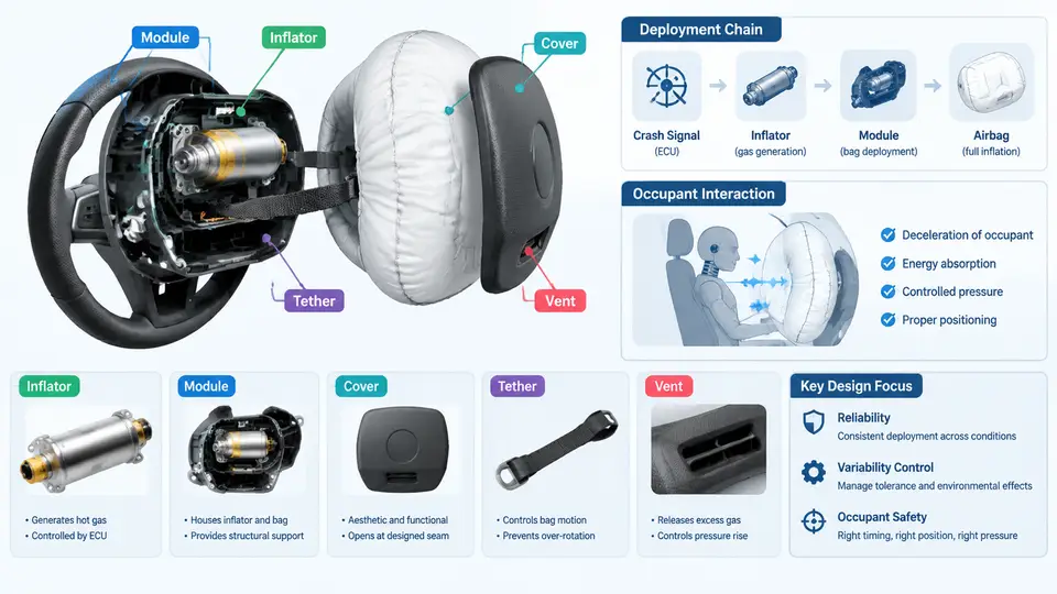
An airbag is not a single product but a chain of tightly coupled subsystems that must all function within a few tens of milliseconds. Understanding deployment variability begins with understanding this chain: the inflator that generates gas, the module that houses and aims it, the cover that opens at the right moment, the tether that shapes the cushion, the vent that regulates internal pressure, and finally the occupant whose position and motion determine whether the restraint actually helps. Variability introduced at any link propagates downstream and shows up as scatter in occupant injury metrics. This chapter maps the architecture and traces the deployment chain end to end.
1. The physical stack: from inflator to occupant
A driver-side airbag module is a compact assembly. At its core sits the inflator, a pyrotechnic or hybrid gas generator. On ignition, the initiator fires, the propellant or compressed gas releases energy, and the housing directs hot gas through a diffuser into the cushion. The cushion is folded in a controlled pattern so that it unfolds predictably rather than tangling. A cover with a tear seam retains the folded cushion and splits open when internal pressure reaches a threshold. Inside the cushion, tethers limit how far the cushion extends, and vents (or active venting valves) bleed gas to soften the interaction with the occupant.
Each element has a distinct role in the timing budget. The inflator determines the mass-flow rate and total gas output. The module and cover determine when the cushion is released and in which direction it travels. The tether and vent determine the cushion's final shape and stiffness. The occupant's position, mass, and belt usage determine how that cushion is actually loaded. Deployment variability is therefore not one phenomenon but the superposition of manufacturing tolerances, environmental conditions, and occupant-state uncertainty across this stack.
2. The deployment chain as a timed sequence
The chain is best understood as a sequence of events with characteristic times. A typical frontal crash pulse triggers the sensing and diagnostic module (SDM) to decide on deployment within roughly 10–20 ms. The inflator then produces gas over a burn or discharge window of about 20–40 ms. The cushion inflates and the cover tears open, and the cushion reaches the occupant at roughly 30–50 ms after impact, depending on occupant position. The vent then regulates pressure during the ride-down phase.
Two timing relationships dominate robustness. First, the time-to-fire must be short enough that the cushion is fully deployed before the occupant moves into the deployment zone, yet not so early that it is already deflating when the occupant arrives. Second, the cover opening time must be consistent; a cover that opens late or asymmetrically changes the cushion trajectory and can cause the cushion to load the occupant off-center. These are not independent: inflator output, cover stiffness, and cushion fold pattern interact, which is why airbag development is iterative rather than sequential.
3. Where variability enters
Variability has several distinct sources, and separating them is essential for robust design.
- Inflator variability: propellant mass, grain geometry, and ambient temperature change the burn rate and total gas output. A cold inflator produces gas more slowly; a hot one faster. This shifts the entire pressure-time curve.
- Module and cover variability: tear-seam depth, material lot, and aging affect the opening pressure and the symmetry of the split. A seam that is too strong delays opening; too weak and the cover may fragment.
- Cushion variability: fold pattern repeatability, fabric permeability, and tether stitch strength determine how the cushion unfolds and how much gas it retains.
- Vent variability: fixed vents are simple but passive; active vents add a control element but also a new failure mode and a new source of scatter.
- Occupant variability: stature, seating position, belt routing, and out-of-position (OOP) states change the effective interaction. A 5th-percentile female and a 95th-percentile male load the same cushion very differently.
The engineering consequence is that a design that works at nominal conditions may fail at the tails. Robust design means making the occupant response insensitive to these sources, not merely optimizing the nominal case.
4. Reading the chain as a signal and energy path
It helps to view the deployment chain as an energy and signal path. The crash pulse is the input signal; the SDM converts it into a fire command; the inflator converts chemical energy into gas pressure; the cushion converts pressure into a force-displacement interaction with the occupant; the occupant's body converts that interaction into acceleration and injury metrics. Variability can be injected at any conversion stage, and the sensitivity of the final injury metric to each stage differs. A robust design identifies which conversions dominate the scatter and controls those first.
5. From architecture to robust design
The architecture above tells us where to look, but robust design requires quantifying how much each link contributes to the final scatter. A practical approach is to treat the chain as a transfer function: input crash pulse → inflator output → cushion pressure → occupant force → injury metric. Sensitivity analysis, whether through physical testing or simulation, identifies which transfer stages amplify variability. In many frontal systems, the inflator output and the occupant position dominate; in side systems, the cushion geometry and the gap to the occupant often dominate.
Once the dominant stages are known, robustness strategies become concrete. For inflator variability, one can specify a tighter burn-rate window or design the cushion to tolerate a wider pressure range. For cover variability, one can control tear-seam depth statistically and validate at the tolerance extremes. For occupant variability, one can use adaptive venting or dual-stage inflators that adjust output based on sensed occupant state. The common thread is that robustness is achieved by reducing sensitivity, not by chasing a single nominal optimum.
6. A worked framing example
Consider a frontal driver airbag that shows higher-than-expected scatter in chest deflection during a 56 km/h rigid-barrier test series. The nominal design passes, but the upper tail exceeds the target. Tracing the chain: the crash pulse is well controlled, so the SDM stage is stable. The inflator lot shows a burn-rate spread of ±8% at temperature extremes. The cover tear seam varies with material lot, shifting opening time by several milliseconds. The cushion fold is consistent, but the vent orifice tolerance adds another few percent to peak pressure. The occupant position in the test matrix varies by ±30 mm.
A robustness study would first quantify the contribution of each source — for example, by running a design-of-experiments matrix across inflator burn rate, cover opening time, vent orifice, and occupant position. If the inflator and occupant position dominate, the design response might be a tighter inflator specification plus an adaptive vent that compensates for occupant proximity. If the cover dominates, the response is statistical process control on the tear seam and validation at the seam-strength extremes. The point is that the architecture tells you what to vary; the sensitivity analysis tells you what matters.
This chapter has established the deployment chain as the organizing framework for the rest of the course. Every subsequent topic — inflator characterization, cover design, cushion folding, vent strategies, occupant modeling, and robustness methods — attaches to one or more links in this chain. Keeping the chain in view prevents local optimization from undermining system-level performance.