1. Bolted and frictional assemblies in engi
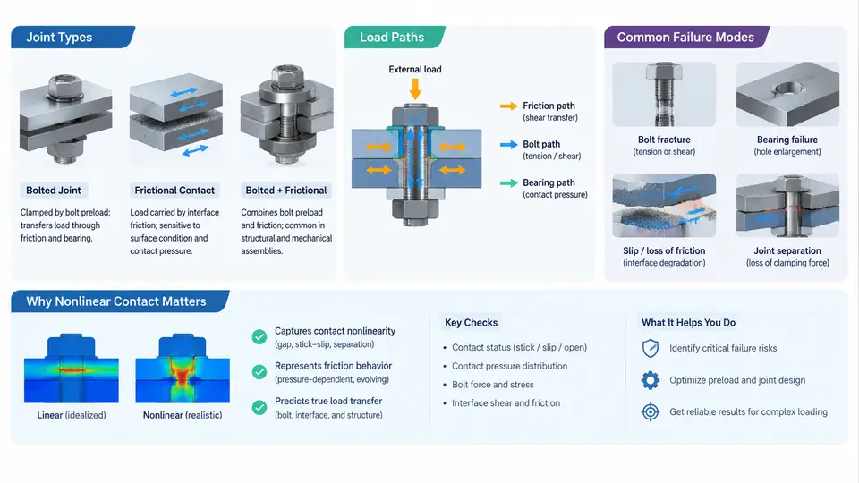
Bolted joints are among the most common structural connections in mechanical, aerospace, civil, and energy systems, yet they are also among the most frequently misrepresented in finite element analysis. The reason is straightforward: a bolted joint is not a single structural element but a system whose stiffness, load capacity, and failure behavior depend on contact between multiple bodies, preload in the fastener, friction at the interfaces, and the local plasticity that develops as the joint is loaded. Linear static analysis with bonded contacts can predict nominal stress fields, but it cannot capture the load redistribution that occurs when contact surfaces separate, when friction is overcome, or when the bolt yields. This chapter establishes the physical and mechanical foundation for the nonlinear contact simulation methods developed throughout the course.
Joint Types and Their Mechanical Character
Bolted connections are typically classified by the way they transfer load across the interface. The three primary categories are tension joints, shear joints, and combined tension-shear joints. In a tension joint, the external load acts along the bolt axis, and the fastener must resist separation of the clamped members. The preload compresses the interface, and the joint remains closed as long as the external tension does not exceed the preload minus any loss from embedding or relaxation. In a shear joint, the load acts perpendicular to the bolt axis, and the interface friction carries the load until slip occurs; beyond slip, the bolt shank or the hole bearing surface carries the load through bearing and shear. Combined joints, common in brackets and flanges, transfer load through both mechanisms simultaneously, and the interaction between them is strongly nonlinear.
A second classification concerns the number and arrangement of fasteners. Single-bolt joints are rarely used in primary structure because they provide no redundancy and poor rotational restraint. Multi-bolt patterns—whether in a line, a rectangular grid, or a circular flange—distribute load unevenly. The bolts at the ends of a row typically carry more load than interior bolts because the connected plates are stiffer near the load introduction point. This non-uniform distribution is a direct consequence of the elastic interaction between the plate, the fasteners, and the contact interfaces, and it cannot be predicted by simple bolt-group formulas when the joint is loaded beyond the elastic range.
Load Paths Through a Bolted Joint
Understanding load paths is essential for interpreting simulation results. Consider a typical lap shear joint with two plates and a single bolt. The external load enters the upper plate, travels toward the bolt hole, and is transferred to the lower plate through three parallel mechanisms: friction at the faying surface, bearing at the hole boundary, and shear in the bolt shank. Before slip, friction carries nearly all the load, and the bolt experiences little shear. Once the friction force reaches the product of the friction coefficient and the normal force at the interface, the plates begin to slide, and the bolt shank contacts the hole wall. From that point, the load path shifts progressively to bearing and bolt shear.
In a tension joint, the load path is different. The external tension is applied to the clamped members, and the bolt elongates while the members unload. The stiffness of the joint is a series combination of the bolt stiffness and the member stiffness, and the fraction of external load carried by the bolt depends on the ratio of these stiffnesses. This is the well-known joint stiffness ratio, often denoted by the symbol C. For a typical steel joint with a long grip length, C may be as low as 0.1, meaning only 10% of the external load reaches the bolt. For a short grip or a soft gasket, C can exceed 0.5, and the bolt becomes the critical load path.
Failure Modes That Motivate Nonlinear Simulation
Bolted joints fail in several distinct ways, and each failure mode is associated with a specific nonlinear mechanism. The most common modes are:
- Bolt tensile failure: The bolt fractures when the tensile stress in the shank exceeds the ultimate strength. This mode is governed by preload, joint stiffness ratio, and the applied external load.
- Thread stripping: The threads in the nut or the tapped hole shear off when the engaged length is insufficient or the material is too soft. This is a contact-dominated failure involving the thread flanks.
- Bearing failure of the plate: The hole elongates when the bearing stress exceeds the plate material's yield strength. This mode is common in thin plates and aluminum structures.
- Net-section rupture: The plate tears across the reduced cross-section through the hole when the net-section stress reaches the ultimate strength.
- Shear tear-out: The plate material between the hole and the free edge shears out when the edge distance is too small.
- Slip and fretting fatigue: Repeated micro-slip at the interface causes fretting wear and initiates fatigue cracks. This mode is particularly sensitive to contact pressure and friction coefficient.
- Self-loosening: Cyclic loading or vibration causes the bolt to rotate and lose preload. This is a contact-driven phenomenon involving the thread and bearing surfaces.
Each of these modes involves contact nonlinearity, material nonlinearity, or both. Bolt tensile failure requires accurate preload and stiffness ratio, which depend on contact at the interfaces. Thread stripping requires modeling the thread geometry and the contact pressure distribution along the engaged threads. Bearing failure requires capturing the local plasticity at the hole boundary. Fretting fatigue requires resolving the micro-slip amplitude and the contact pressure history. None of these can be predicted reliably with linear analysis and bonded contacts.
Why Nonlinear Contact Simulation Is Necessary
The central difficulty in bolted joint analysis is that the joint stiffness and load distribution are emergent properties of the contact state. When two surfaces are in contact, they transmit compressive normal stress and, if friction is present, shear stress. When they separate, they transmit nothing. When they slide, the shear stress is limited by the friction coefficient times the normal stress. These conditions are inequality constraints, and they make the problem nonlinear even if the materials remain elastic.
Consider a simple example: a single-bolt lap joint with two steel plates, each 6 mm thick, a 10 mm diameter bolt, and a friction coefficient of 0.2. The bolt is preloaded to 20 kN. If the external shear load is 3 kN, the friction force required to prevent slip is 3 kN, which is less than the friction capacity of 4 kN (0.2 × 20 kN). The joint does not slip, and the bolt carries almost no shear. If the external load increases to 5 kN, the friction capacity is exceeded, and the plates slip until the bolt shank contacts the hole wall. The bolt now carries 5 kN in shear, and the contact pressure at the hole boundary becomes highly non-uniform. A linear analysis with bonded contact would predict the same bolt shear at both load levels, which is physically wrong.
This example illustrates the core motivation for nonlinear contact simulation: the load path is load-history dependent, and the transition from friction-dominated to bearing-dominated load transfer is a nonlinear event that must be captured explicitly. The same principle applies to tension joints, where separation of the interface changes the effective stiffness, and to multi-bolt joints, where progressive slip redistributes load among the fasteners.
Practical Implications for Simulation Strategy
The physical picture developed above leads directly to several simulation requirements. First, the contact interfaces must be modeled with a finite friction coefficient and an appropriate contact algorithm—penalty or Lagrange multiplier—that can handle both sticking and sliding. Second, the bolt preload must be applied as an initial condition, typically through a thermal contraction, an initial stress, or a bolt preload element. Third, the analysis must be performed in multiple load steps so that the contact state can evolve gradually and the solver can converge. Fourth, material plasticity should be included when the bearing stress or the net-section stress approaches yield, because the load redistribution after yielding is significant.
A useful sanity check before running a full nonlinear simulation is to estimate the slip load and the bearing load separately. For the example above, the slip load is μ·N = 0.2 × 20 kN = 4 kN. The bearing capacity of the 6 mm plate with a 10 mm bolt and a 400 MPa yield strength is approximately d·t·σy = 10 × 6 × 400 = 24 kN. The bolt shear capacity is roughly 0.6 × As × σu, which for an M10 property class 8.8 bolt is about 0.6 × 58 mm² × 800 MPa ≈ 27.8 kN. These estimates tell the analyst which failure mode is likely to dominate and where to focus mesh refinement and contact definition.
From Physical Understanding to Simulation Practice
The remainder of this course builds on the foundation established here. The next chapters will cover the mechanics of contact constraints, the formulation of friction models, the application of bolt preload, the treatment of material nonlinearity, and the solution strategies that make these simulations converge. Each of these topics is motivated by the physical behaviors described in this chapter: the transition from friction to bearing, the change in load path as contact conditions evolve, and the failure modes that emerge when the joint is pushed beyond its elastic limit. A clear understanding of joint types, load paths, and failure modes is not merely background—it is the basis for every modeling decision that follows.