1. Introduction to fracture mechanics
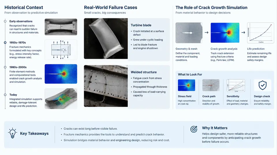
Fracture mechanics is the engineering discipline that quantifies how cracks initiate, propagate, and eventually cause structural failure. It provides the analytical framework that connects material properties, applied loads, component geometry, and crack size into a single predictive model. Without this framework, engineers would be forced to rely on empirical safety factors alone—an approach that historically produced catastrophic and sometimes fatal results.
1.1 Historical Context: From Empirical Rules to Predictive Science
The modern field emerged from a series of structural failures that exposed the limitations of strength-based design. In the early twentieth century, welded Liberty ships operating in cold North Atlantic waters suffered brittle fracture failures despite being constructed from steel that passed standard tensile tests. The fractures initiated at weld toes and stress concentrations, then propagated rapidly through the hull with almost no plastic deformation. Investigators found that the steel's Charpy V-notch impact energy at low temperature was insufficient to arrest a running crack, even though its yield strength met specification.
These failures motivated a fundamental shift: instead of asking only "is the stress below yield?", engineers began asking "will an existing crack grow to critical size under service loading?" This question defines the core problem of fracture mechanics.
Key milestones in the field's development include:
- Griffith (1920): Proposed an energy-balance criterion for crack growth in brittle materials, relating crack extension to the release of elastic strain energy and the creation of new surface energy.
- Irwin (1957): Extended Griffith's work to ductile metals by introducing the energy release rate G and the stress intensity factor K, establishing the foundation of linear elastic fracture mechanics (LEFM).
- Paris and Erdogan (1963): Demonstrated that fatigue crack growth rate da/dN correlates with the stress intensity range ΔK through a power-law relationship, now known as the Paris law.
- Rice (1968): Introduced the J-integral, enabling fracture analysis of materials with significant plastic deformation.
1.2 Failure Case Studies That Shaped Design Practice
Three case studies illustrate how fracture mechanics directly influences engineering codes and design decisions.
Comet jetliner accidents (1954). Two de Havilland Comet aircraft disintegrated in flight due to fatigue cracking originating at square-cut window corners. The stress concentration at these corners accelerated crack initiation under repeated cabin pressurization cycles. The investigation led to the now-universal practice of rounded window corners and the application of damage tolerance principles in aerospace design.
Aloha Airlines Flight 243 (1988). A Boeing 737 lost a large section of its upper fuselage when multisite fatigue damage along rivet rows exceeded the residual strength of the skin. This event drove the adoption of widespread fatigue damage (WFD) assessment requirements and mandatory structural teardown inspections for aging aircraft.
Alexander L. Kielland platform capsize (1980). A semi-submersible drilling rig capsized in the North Sea after a fatigue crack propagated from a fillet weld on a bracing member. The crack had initiated years earlier and grown undetected because the inspection interval did not account for the actual stress range at that detail. This case reinforced the need for fracture-mechanics-based inspection planning rather than fixed-interval schedules.
1.3 The Role of Crack Growth Simulation in Engineering Design
Crack growth simulation applies the mathematical models of fracture mechanics to predict how a crack will evolve under a specified loading history. In practice, this means solving for the stress intensity factor at the crack tip, integrating a crack growth law over load cycles, and determining when the crack reaches a critical size or the structure's residual strength falls below a required threshold.
The simulation workflow typically involves the following inputs and outputs:
| Input | Description | Typical Source |
|---|---|---|
| Initial crack size a₀ | Assumed or measured defect size | NDI detection limit, manufacturing quality data |
| Geometry factor β | Dimensionless function of crack and component geometry | Handbooks, finite element analysis |
| Stress range Δσ | Cyclic stress amplitude at the crack location | Load spectrum, strain gauge data |
| Material constants C, m | Paris law parameters | ASTM E647 testing |
| Fracture toughness KIC | Critical stress intensity for unstable fracture | ASTM E399 testing |
The output is a crack growth curve: crack size a versus elapsed cycles N. From this curve, the engineer determines the inspection interval by finding the number of cycles for the crack to grow from the detectable size to the critical size, then applying a safety factor (typically 2 on life or 0.5 on detectable size, depending on the standard).
A simple Paris law integration for constant-amplitude loading illustrates the calculation:
da/dN = C * (ΔK)^m
ΔK = β * Δσ * sqrt(π * a)

Integrating from a₀ to a_c:
N_f = ∫[a₀ to a_c] da / [C * (β * Δσ * sqrt(π * a))^m]

For m ≠ 2, the closed-form solution is:
N_f = [a_c^(1-m/2) - a₀^(1-m/2)] / [C * (β * Δσ * sqrt(π))^m * (1 - m/2)]
As a concrete example, consider a 2024-T351 aluminum panel with an edge crack. Assume a₀ = 2 mm, β = 1.12 (edge crack geometry factor), Δσ = 80 MPa, C = 1.5 × 10⁻¹¹ (MPa, m units), m = 3.2, and KIC = 35 MPa·√m. The critical crack size is found from KIC = β Δσ √(π ac), giving ac ≈ 15.2 mm. Integrating the Paris law yields a predicted fatigue life of approximately 48,000 cycles. This is a representative calculation for illustration; actual values depend on the specific material batch and loading spectrum.
1.4 Why Simulation Matters in Design
Physical testing alone cannot cover the full range of loading histories, environmental conditions, and defect sizes that a structure may encounter. Crack growth simulation fills this gap by allowing engineers to:
- Set rational inspection intervals based on predicted crack growth rates rather than arbitrary calendar periods.
- Evaluate residual strength at any point in the component's life, ensuring that a detectable crack will not cause catastrophic failure before the next inspection.
- Compare design alternatives — for example, selecting a material with higher fracture toughness or modifying a detail to reduce the stress intensity factor.
- Support damage tolerance certification required by aerospace, nuclear, and pressure vessel codes (e.g., FAA AC 25.571, ASME Section XI, BS 7910).
1.5 Scope of This Course
This course progresses from the theoretical foundations of linear elastic and elastic-plastic fracture mechanics through to practical simulation workflows. Subsequent chapters cover stress intensity factor calculation methods, fatigue crack growth modeling under variable amplitude loading, numerical implementation using finite element analysis, and validation against experimental data. The goal is to equip you with the ability to build, interpret, and critically evaluate crack growth simulations for real engineering components.
By the end of this course, you should be able to select appropriate fracture mechanics parameters for a given material and loading condition, construct a crack growth model using standard tools, and use simulation results to make defensible decisions about inspection intervals, allowable stress levels, and remaining life assessments.