1. Industrial FEA workflow
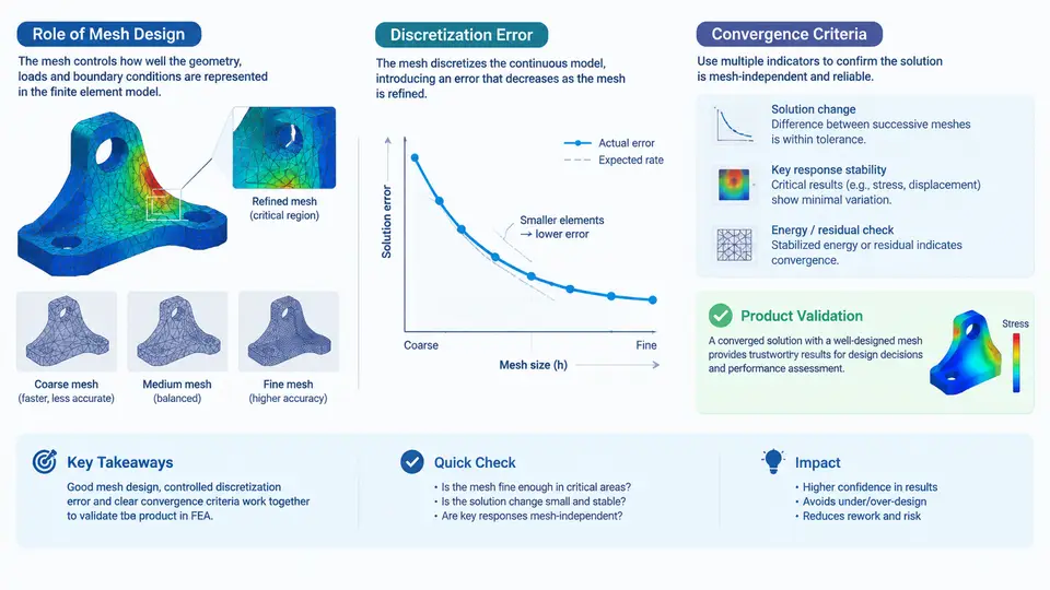
In industrial finite element analysis, the mesh is not a preprocessing formality—it is the numerical model's constitutive approximation of the physical domain. Every result a solver produces is conditioned on how that domain was discretized. Understanding the relationship between mesh design, discretization error, and convergence criteria is therefore the foundation of defensible product validation.
The Industrial FEA Workflow and Where Mesh Design Sits
A typical industrial FEA workflow proceeds through geometry preparation, material and boundary condition definition, mesh generation, solution, and post-processing. Mesh design sits at the critical junction between the idealized CAD geometry and the numerical solution. It determines:
- Geometric fidelity — how accurately curved surfaces, fillets, and thin features are represented by elements.
- Solution resolution — whether stress gradients, contact pressures, and thermal fields are captured with adequate spatial sampling.
- Computational cost — element count, degrees of freedom (DOF), solver memory, and wall-clock time.
In product validation, the mesh must be fine enough that the quantities of interest (QoI)—peak von Mises stress, fatigue hot-spot location, stiffness, natural frequency—are insensitive to further refinement. If they are not, the validation conclusion is unreliable regardless of how well the boundary conditions were defined.
Discretization Error: Sources and Behavior
Discretization error is the difference between the exact solution of the governing partial differential equations and the solution of the discretized algebraic system. It has two principal components:
- Local truncation error — introduced by approximating derivatives with element shape functions. For a polynomial of order p on an element of size h, the error in the energy norm scales as O(hp).
- Quadrature and integration error — from numerical integration of element stiffness matrices, typically negligible for standard reduced/full integration schemes but relevant for highly distorted elements.
Discretization error is not uniform across the model. It concentrates where the solution has high curvature: stress concentrations at holes, fillets, contact edges, crack tips, and regions with rapid thermal gradients. A mesh that is uniformly refined wastes DOF in smooth regions while remaining under-resolved at hot spots.
Convergence Criteria: What to Measure and When to Stop
Convergence criteria define the stopping condition for mesh refinement. In industrial practice, three approaches dominate:
| Criterion | What It Measures | Typical Industrial Threshold | Limitation |
|---|---|---|---|
| Global energy norm | Strain energy error estimate | < 5% change between refinements | May mask local hot-spot error |
| Local QoI convergence | Peak stress, displacement, frequency | < 2–5% change over two consecutive refinements | Requires consistent extraction location |
| Error estimator (ZZ, SPR) | Element-level error distribution | All elements below target error density | Estimator quality varies with problem type |
For product validation, local QoI convergence is the most defensible criterion. A global energy norm may converge while the peak stress at a fillet continues to rise by 10–15% with each refinement. The validation engineer must identify the QoI before meshing begins and track it explicitly.
Practical Mesh Design Decisions
Industrial mesh design balances competing constraints. Consider a bracket subjected to static loading, with a fillet radius of 5 mm and a nominal global element size of 4 mm. A reasonable strategy:
- Global seed: 4 mm quadratic tetrahedra (C3D10) or 4 mm shell elements, giving a baseline model of roughly 80,000–150,000 DOF.
- Local refinement at the fillet: bias element size to 0.5–1.0 mm within a 10 mm sphere around the fillet, using curvature-based or proximity-based sizing.
- Through-thickness resolution: at least 2–3 elements through the thickness of any bending-dominated member to capture the linear stress gradient.
- Quality checks: aspect ratio < 5 for tetrahedra in stress-critical regions, Jacobian ratio > 0.6, and no negative Jacobians.
After solving, extract the peak von Mises stress at the fillet and compare across three mesh densities: coarse (global 4 mm, no local refinement), medium (global 4 mm + 1 mm fillet refinement), and fine (global 2 mm + 0.5 mm fillet refinement). If the peak stress changes by less than 3% between medium and fine, the medium mesh is converged for that QoI.
Visualizing the Mesh–Error–Convergence Relationship
The following diagram illustrates how mesh refinement drives discretization error down and how convergence criteria gate the validation decision. It shows the feedback loop between local error estimation, adaptive refinement, and QoI tracking.
Applying the Workflow: A Validation Scenario
Consider a cast aluminum housing for an electric motor, validated for structural integrity under a 3g inertial load. The QoI is the peak von Mises stress at a bolt boss fillet, with a material yield strength of 240 MPa and a required safety factor of 1.5 (allowable 160 MPa).
Step 1 — Baseline mesh: Global element size 5 mm, quadratic tetrahedra, 120,000 DOF. Solve and extract peak stress: 178 MPa. This exceeds the allowable, but the mesh is coarse at the fillet.
Step 2 — Local refinement: Apply 1 mm element size within 8 mm of the fillet. DOF increases to 310,000. Peak stress rises to 195 MPa—a 9.5% increase. The coarse mesh was under-predicting the hot spot.
Step 3 — Further refinement: Apply 0.5 mm element size at the fillet. DOF reaches 620,000. Peak stress: 199 MPa—a 2.1% increase from the previous level. The QoI is converging.
Step 4 — Decision: The change from medium to fine is 2.1%, below the 3% threshold. The fine mesh result of 199 MPa is accepted as converged. Safety factor = 240/199 = 1.21, which is below the required 1.5. The design must be modified—either increase fillet radius or change material.
This example demonstrates that mesh convergence is not an academic exercise. The difference between the coarse (178 MPa) and converged (199 MPa) results is 12%, which could mean the difference between a passing and failing validation. In industrial practice, accepting an unconverged mesh is a common source of field failures.
Key Takeaways for Industrial Practice
- Define the QoI before meshing. Convergence criteria must be tied to the quantity that drives the validation decision.
- Refine locally, not globally. Adaptive h-refinement at high-error regions is more efficient than uniform refinement.
- Use at least three mesh levels for convergence studies. Two levels cannot distinguish between convergence and coincidence.
- Track the QoI, not just global energy. A converged energy norm does not guarantee a converged local stress.
- Document the convergence study. In regulated industries (aerospace, medical, automotive), the mesh convergence evidence is part of the validation record.
Mesh design, discretization error, and convergence criteria form a closed loop: the mesh determines the error distribution, the error distribution guides refinement, and the convergence criterion determines when the loop terminates. Mastering this loop is what separates a numerical exercise from a reliable product validation.