1. Side impact crash simulation in LS-DYNA
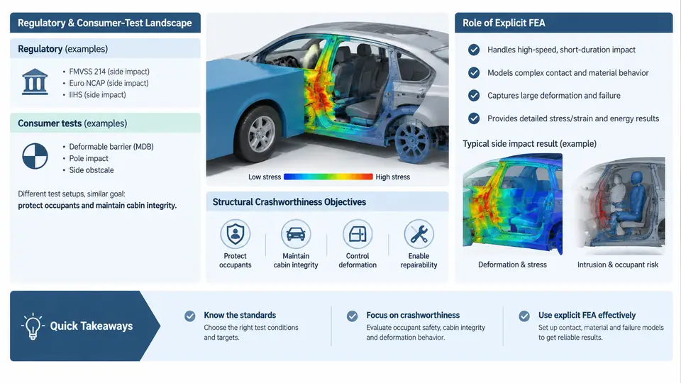
Side impact is one of the most demanding load cases in automotive body-in-white (BIW) engineering. Unlike frontal crashes, where a long crumple zone can absorb energy progressively, the lateral load path between the striking barrier and the occupant is measured in a few hundred millimetres. The door trim, B-pillar, rocker, roof rail, seat structure, and floor cross-members must dissipate energy within a very short stroke while preserving a survival space around the occupant. LS-DYNA, with its explicit time-integration solver, is the industry-standard tool for predicting this behaviour before a single prototype is built.
1.1 The Regulatory and Consumer-Test Landscape
Side impact performance is governed by two parallel families of tests: government regulation and consumer rating programmes. Both must be satisfied, but they differ in barrier geometry, impact velocity, occupant reference, and pass/fail criteria.
| Test | Barrier / Striker | Impact Speed | Primary Metric |
|---|---|---|---|
| FMVSS 214 (US, rigid moving deformable barrier) | MDB, 1,368 kg, crabbed 27° | 54 km/h | Rib deflection, pelvic force, spinal acceleration |
| UN ECE R95 (Europe, deformable barrier) | MDB, 950 kg, perpendicular | 50 km/h | Rib deflection, abdominal force, pelvic force |
| Euro NCAP side mobile progressive deformable barrier (MPDB) | MDB, 1,400 kg, 50% overlap | 50 km/h | Compatibility, occupant loading, structural intrusion |
| Euro NCAP side pole | Rigid pole, 254 mm diameter | 32 km/h | Head, thorax, abdomen, pelvis injury criteria |
| IIHS side impact | MDB, 1,905 kg, 25° crabbed | 60 km/h | Intrusion, dummy injury measures, structural rating |
Two observations matter for the CAE engineer. First, the barrier mass and velocity determine the kinetic energy that the vehicle structure must absorb. The IIHS 1,905 kg barrier at 60 km/h carries roughly 264 kJ, whereas the ECE R95 barrier at 50 km/h carries about 92 kJ — a factor of nearly three. Second, the pole test concentrates the load on a narrow contact patch, which produces severe local deformation and is often the sizing case for the B-pillar and roof rail.
1.2 Crashworthiness Objectives for Side Impact
The structural engineer translates the test requirements into a set of quantifiable objectives. These typically include:
- Intrusion limits: maximum lateral displacement of the door inner panel, B-pillar, and rocker relative to the occupant seating reference point. A common internal target is to keep B-pillar intrusion below 120–150 mm at the occupant hip and chest height.
- Energy absorption: the total internal energy absorbed by the door, B-pillar, rocker, floor, and seat structure must match the barrier kinetic energy minus the residual velocity of the vehicle.
- Force–displacement characteristics: the B-pillar and rocker should exhibit a stable, progressive collapse rather than a sharp peak followed by a drop, which would indicate buckling or joint failure.
- Occupant injury criteria: rib deflection, viscous criterion (VC), abdominal force, pelvic force, and head injury criterion (HIC) must remain below the thresholds defined by the regulation or rating programme.
- Mass and packaging: the reinforcement strategy must fit within the available door and pillar section, and must not add excessive mass.
These objectives are not independent. Adding a thick B-pillar reinforcement reduces intrusion but may increase the peak force transmitted to the occupant, raising rib deflection. The engineer must therefore evaluate the complete load path, not just individual components.
1.3 Why Explicit FEA Is the Right Tool
Side impact involves large deformation, contact, material failure, and strain-rate effects. Implicit solvers struggle with the severe nonlinearity and contact changes that occur within the 50–100 ms event. LS-DYNA's explicit central-difference scheme advances the solution one small time step at a time, using the courant condition to ensure stability. The critical time step is approximately the smallest element characteristic length divided by the wave speed in the material. For a typical steel door panel with a 5 mm element and a wave speed of about 5,000 m/s, the stable time step is on the order of 1 microsecond, requiring roughly 50,000–100,000 cycles for a 50–100 ms simulation.
The explicit approach also handles contact naturally. LS-DYNA's penalty-based contact algorithms detect penetration between the barrier, door, B-pillar, seat, and dummy, and apply restoring forces without requiring the user to define contact pairs manually in most cases. This is essential when the deformation pattern is not known in advance.
1.4 The Simulation Workflow in Context
A side impact simulation in LS-DYNA follows a logical sequence: build the barrier and vehicle model, define material models and section properties, set up contact and boundary conditions, apply the initial velocity, run the explicit solver, and post-process the results. The figure below shows the relationship between the test configuration, the structural load path, and the simulation outputs that the engineer must evaluate.
1.5 From Test Protocol to Simulation Input
Translating a test protocol into a reliable LS-DYNA model requires attention to several details that are easy to overlook. The barrier must be modelled with the correct mass distribution and deformable honeycomb characteristics; a rigid barrier will over-predict intrusion. The initial velocity must be applied to the entire vehicle model, not just the barrier, unless the test setup specifies a stationary vehicle. The ground plane must be represented with a rigid wall or a contact definition that prevents the vehicle from dropping through the floor.
Material models deserve particular care. For high-strength steel B-pillar reinforcements, a strain-rate-dependent plasticity model such as MAT_024 (piecewise linear plasticity) with a defined stress–strain curve at multiple strain rates is appropriate. For aluminium door beams, MAT_098 or MAT_103 may be used. For the honeycomb barrier, MAT_026 (honeycomb) or MAT_063 (crushable foam) captures the plateau stress behaviour. The choice of element formulation — fully integrated versus reduced integration with hourglass control — affects both accuracy and runtime.
1.6 Key Takeaways
- Side impact tests differ significantly in barrier mass, velocity, and geometry; the simulation must match the specific protocol being evaluated.
- Crashworthiness objectives include intrusion limits, energy absorption, stable force–displacement behaviour, and occupant injury criteria.
- Explicit FEA in LS-DYNA is well suited to the large deformation, contact, and strain-rate effects present in side impact.
- Energy balance and hourglass energy are essential sanity checks before trusting any result.
- The simulation workflow is iterative: build, run, evaluate, modify, and re-run until all targets are met.
With this foundation, subsequent chapters will move into the detailed modelling techniques — mesh generation, material calibration, contact definition, and occupant restraint modelling — that turn a conceptual model into a predictive engineering tool.