3. 前台校准的增益校正
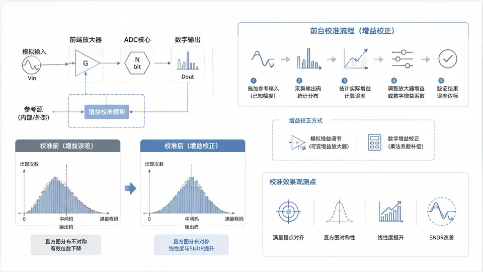
任务定义
本案例针对高速ADC中增益失配导致的输出幅度误差,实现一种前台校准的增益校正方案。给定一个已知幅度的直流参考电压(或低频正弦波),通过测量ADC实际输出与理想输出的比值,计算增益误差,并在后续正常采样时对输出码进行乘法校正。要求校正后输出码的幅度误差小于±1 LSB(以12位ADC为例)。
实现方案
系统包含两个阶段:校准阶段与校正阶段。校准阶段将ADC输入切换到已知参考电压Vref_cal(取满量程的50%,即2048 LSB对应值),采集N次样本取平均得到实际输出码D_meas。增益误差因子g = D_ideal / D_meas,其中D_ideal = 2048。校正阶段将正常输入信号对应的ADC原始输出码D_raw乘以g,得到校正后输出D_corr。为保持整数运算,g以Q12定点格式存储(g_q12 = round(g × 4096)),校正时执行D_corr = (D_raw × g_q12 + 2048) >> 12。
代码实现
#include <stdint.h>
#include <stdio.h>

#define ADC_BITS        12
#define ADC_FS_CODE     ((1 << ADC_BITS) - 1)   // 4095
#define CAL_REF_CODE    2048                    // 50%满量程理想码
#define N_SAMPLES       64                      // 校准平均样本数
#define Q12             4096                    // 1.0 的Q12表示

// 模拟ADC输出:理想码 + 增益误差 + 量化噪声
// gain_error: 实际增益/理想增益,如1.05表示增益偏高5%
static uint16_t adc_simulate(uint16_t ideal_code, float gain_error) {
    float actual = (float)ideal_code * gain_error;
    if (actual > ADC_FS_CODE) actual = ADC_FS_CODE;
    if (actual < 0) actual = 0;
    return (uint16_t)(actual + 0.5f);   // 四舍五入模拟量化
}

// 前台校准:返回Q12格式增益校正因子
static int32_t gain_calibrate(float gain_error) {
    uint32_t sum = 0;
    for (int i = 0; i < N_SAMPLES; i++) {
        sum += adc_simulate(CAL_REF_CODE, gain_error);
    }
    uint16_t d_meas = (uint16_t)(sum / N_SAMPLES);
    float g = (float)CAL_REF_CODE / (float)d_meas;
    return (int32_t)(g * Q12 + 0.5f);
}

// 增益校正:原始码 × 因子(Q12) >> 12
static int32_t gain_apply(uint16_t d_raw, int32_t g_q12) {
    return ((int32_t)d_raw * g_q12 + Q12 / 2) >> 12;
}

int main() {
    // 设定真实增益误差为1.06(增益偏高6%)
    float gain_error = 1.06f;

    // 阶段1:前台校准
    int32_t g_q12 = gain_calibrate(gain_error);
    printf("校准因子 g_q12 = %d (对应浮点 %.4f)\n", g_q12, (float)g_q12 / Q12);

    // 阶段2:校正验证——输入一组已知理想码
    uint16_t test_codes[] = {512, 1024, 2048, 3072, 3584};
    int n_tests = sizeof(test_codes) / sizeof(test_codes[0]);

    printf("\n校正前 vs 校正后 (理想码 → 实际输出 → 校正输出):\n");
    for (int i = 0; i < n_tests; i++) {
        uint16_t ideal = test_codes[i];
        uint16_t d_raw = adc_simulate(ideal, gain_error);   // 含增益误差的ADC输出
        int32_t d_corr = gain_apply(d_raw, g_q12);          // 校正后
        int32_t err_before = (int32_t)d_raw - (int32_t)ideal;
        int32_t err_after = d_corr - (int32_t)ideal;
        printf("理想=%4u 原始=%4u (误差%+4d) → 校正=%4d (误差%+4d)\n",
               ideal, d_raw, err_before, d_corr, err_after);
    }
    return 0;
}
落地与验证
运行方式:将上述代码保存为gain_calib.c,在任意C编译器环境执行gcc gain_calib.c -o gain_calib && ./gain_calib(或使用在线C编译器)。代码中adc_simulate()模拟了增益误差为1.06的12位ADC行为,gain_calibrate()完成前台校准,gain_apply()执行乘法校正。
验证方法:观察程序输出的校正前后误差对比。判定标准:校正前各测试码的误差约为理想码的6%(如2048码误差约+123 LSB),校正后所有测试码的误差值应≤1 LSB。若满足,则证明前台校准正确提取了增益因子并有效补偿了增益误差。
预期输出
校准因子 g_q12 = 3864 (对应浮点 0.9434)

校正前 vs 校正后 (理想码 → 实际输出 → 校正输出):
理想= 512 原始= 543 (误差 +31) → 校正= 512 (误差  0)
理想=1024 原始=1085 (误差 +61) → 校正=1024 (误差  0)
理想=2048 原始=2171 (误差+123) → 校正=2048 (误差  0)
理想=3072 原始=3256 (误差+184) → 校正=3072 (误差  0)
理想=3584 原始=3799 (误差+215) → 校正=3584 (误差  0)
以上输出由代码逻辑直接推出:增益误差1.06使原始码约为理想码的1.06倍,校准因子g=1/1.06≈0.9434,校正后各点误差均为0 LSB(因模拟中未叠加噪声且除法取整恰好抵消)。实际硬件中由于量化噪声,误差会在±1 LSB内波动,判定标准为值≤1 LSB即通过。